Comb-shaped bridge expansion joint plate structure and its cleaning device

A cleaning device and technology for expansion joints, applied in bridges, bridge construction, bridge parts, etc., can solve problems such as vehicle tire damage, bridge body damage, and difficulty in replacement, reduce the risk of extrusion collisions, and prevent beams from over-displacement Great, reduce the effect of tire damage

Inactive Publication Date: 2021-04-13
蒋明敏
View PDF37 Cites 0 Cited by
  • Summary
  • Abstract
  • Description
  • Claims
  • Application Information

AI Technical Summary

Problems solved by technology

However, due to the existence of gaps, rainwater will pour into the interior of the bridge and cause damage to the bridge body. In order to prevent rainwater from pouring in, rubber waterstops are usually used for waterstopping of expansion joints in road and bridge construction, and steel plates are anchored on both sides of the expansion joints for protection. , the steel plate is fixedly connected to the two beams. During the deformation process of the beam, the steel plate will be squeezed and deformed. Cause damage and affect the driving comfort of vehicles. With the change of the outdoor environment in our country, the service life of the bridge increases, the rubber is seriously aged and damaged, and it is difficult to replace, resulting in serious leakage at the bridge expansion joints, and the appearance and structure of the bridge are damaged by rain erosion.
The replacement of rubber waterstop is heavy workload, difficult to dispose of, long construction period, and has a great impact on traffic
[0003] The existing comb-shaped bridge expansion joint plates are easily damaged by bridge vibration, and the internal dust and accumulated water are not easy to clean, which affects the service life of the expansion joints

Method used


Image

  • Comb-shaped bridge expansion joint plate structure and its cleaning device
  • Comb-shaped bridge expansion joint plate structure and its cleaning device
  • Comb-shaped bridge expansion joint plate structure and its cleaning device

Examples


Embodiment Construction

[0034] The present invention will be described in detail below in conjunction with the accompanying drawings, so that those of ordinary skill in the art can implement it after referring to this specification.

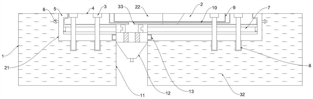
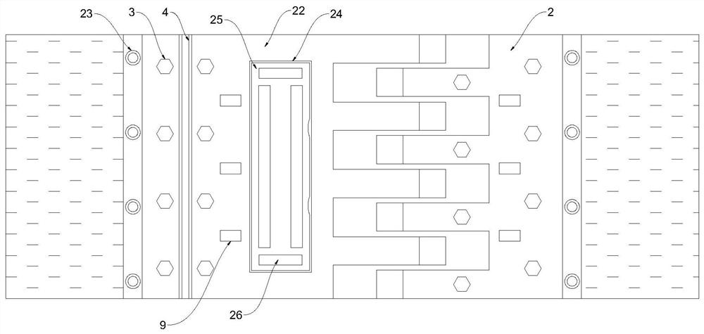
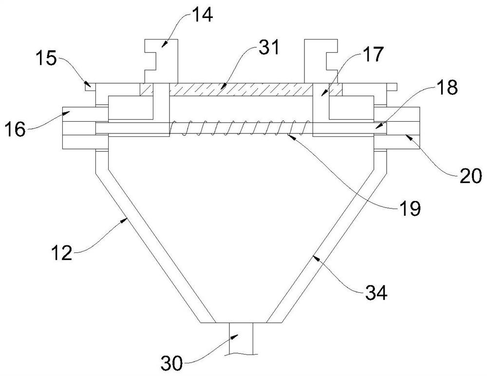
[0035] Such as Figure 1-5As shown, a comb-shaped bridge expansion joint plate structure and its cleaning device include: a first beam body 1, and a second beam body 32 arranged on one side of the first beam body 1, the first beam body The interior of the body 1 and the second beam body 32 is provided with a reserved groove 21, and an expansion joint 11 is provided between the first beam body 1 and the second beam body 32; the comb plate supporting plate 5 is arranged on the Inside the reserved groove 21, the comb-tooth plate supporting plate 5 is fixedly connected with the first beam body 1 and the second beam body 32 through fixing rivets 6; the first comb-tooth type expansion joint plate 22 is arranged on the The inside of the comb-tooth plate supporting plate 5, th...


PUM


Abstract

The invention discloses a comb-shaped bridge expansion joint plate structure and its cleaning device, comprising: a first beam body, and a second beam body arranged on one side of the first beam body, the first beam body and The interior of the second beam body is provided with a reserved groove, and an expansion joint is arranged between the first beam body and the second beam body; the comb tooth plate supporting plate is arranged inside the reserved groove, and the comb teeth The plate supporting plate is fixedly connected with the first beam body and the second beam body respectively through fixed rivets; the first comb-tooth type expansion joint plate is arranged inside the comb-tooth plate supporting plate, and the first comb-tooth type expansion joint plate One side of the slit plate is provided with a second comb-shaped expansion joint plate. It realizes the function of anti-seismic buffer, improves the structural strength of the expansion joint, facilitates the cleaning of accumulated water and dust in the expansion joint, avoids the impact of accumulated water on the internal structure of the expansion joint, and prevents the first beam body and the second beam body from squeezing each other problems that pose safety hazards.

Description

technical field [0001] The invention relates to the technical field of comb-tooth bridge expansion joints, in particular to a comb-tooth bridge expansion joint plate structure and a cleaning device thereof. Background technique [0002] The thermal expansion and contraction of the bridge due to the influence of temperature will have a serious impact on the structure of the bridge body. In order to eliminate this effect, expansion joints are usually set on the bridge, and the expansion joints will follow the bridge body It expands and contracts with heat and contracts with cold, thereby reducing the stress on the bridge. However, due to the existence of gaps, rainwater will pour into the interior of the bridge and cause damage to the bridge body. In order to prevent rainwater from pouring in, rubber waterstops are usually used for waterstopping of expansion joints in road and bridge construction, and steel plates are anchored on both sides of the expansion joints for protecti...

Claims


Application Information

Patent Timeline
Patent Type & Authority Patents(China)
IPC IPC(8): E01D19/06E01D19/08E01H1/08E01F9/524E01F9/559
CPCE01D19/065E01D19/086E01H1/0809E01F9/524E01F9/559
Inventor 蒋明敏盖晖晖王连振邱立超王凯申鹏周子云侯伟乐包晓梅蔡卫华
Owner 蒋明敏
Why Eureka
Try Eureka