Power transmission and power grid conveying frame

A conveying rack and electric power technology, applied in the field of power grid conveying racks, can solve the problems of low practicability, increase construction cost and labor intensity, and cannot adjust the angle and height, so as to improve adaptability and stability, improve practicability and Flexibility, the effect of increasing flexibility and adaptability

Active Publication Date: 2020-12-11
CHONGQING SONGZAO COAL & ELECTRICITY CO LTD
View PDF12 Cites 5 Cited by
  • Summary
  • Abstract
  • Description
  • Claims
  • Application Information

AI Technical Summary

Problems solved by technology

[0007] In order to solve the above-mentioned technical problems, the present invention provides a transmission frame for electric power transmission power grid to solve the problem that the angle and height of the transmission frame on the top of the existing utility pole cannot be adjusted after the installation is completed, and the installation angle of the transmission frame cannot be determined becaus

Method used


Image

  • Power transmission and power grid conveying frame
  • Power transmission and power grid conveying frame
  • Power transmission and power grid conveying frame

Examples


Embodiment

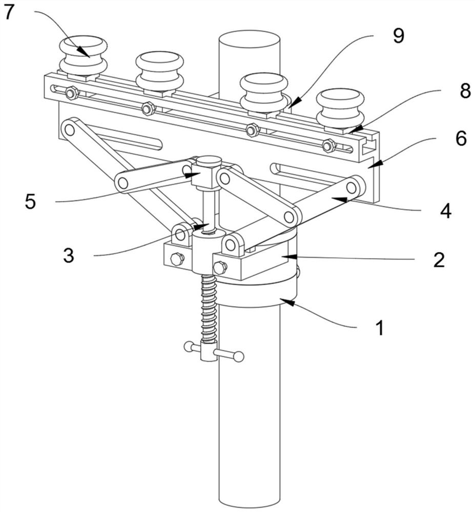
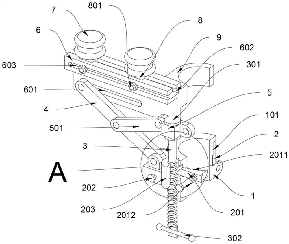
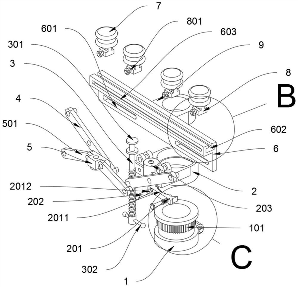
[0036] as attached figure 1 to attach Figure 8 Shown:

[0037] The present invention provides a transmission frame for electric power grid, which includes a fixed base 1, an adjustable base 2, an adjustable rod 3, a support rod 4, a linkage block 5, a support rod 6 and an insulating porcelain bottle 7; the fixed base 1 is screwed and fixed by screws On the top of the utility pole; the top outside of the fixed base 1 is provided with positioning gear teeth 101, and the inside of the adjustment base 2 is provided with a positioning block 201, and the inside of the positioning block 201 is provided with a rack 2011, and the rack 2011 is an arc design , the teeth of the rack 2011 and the teeth of the positioning gear 101 mesh with each other, as attached figure 2 , attached image 3 , attached Figure 4 , attached Figure 6 And attached Figure 8As shown, this design enables the positioning gear teeth 101 to be snapped and engaged by the rack 2011 of the positioning block ...


PUM


Abstract

The invention discloses a power transmission and power grid conveying frame, and relates to the technical field of power grid conveying frames. The problems that when an existing telegraph pole is vertically fixed and then connected, if the angle or position of a top conveying frame does not meet the installation requirement, the top conveying frame needs to be disassembled and reassembled, and the construction cost and the labor intensity can be greatly improved are solved. The power transmission and power grid conveying frame comprises a wire supporting rod, and a rail block is fixedly connected to the middle of the back side of the wire supporting rod. After the device is fixed to the top of the telegraph pole, the angle of the wire supporting rod can still be changed by rotating an adjusting base, the use height of the wire supporting rod can be adjusted by rotating an adjusting rod, the position of a porcelain insulator at the top of the wire supporting rod is changed by moving the position of a sliding block, the device can adapt to cable installation under different conditions, the problem that the angle and the height cannot be adjusted after a traditional conveying frame is installed is solved, and the practicability and the flexibility of the device are improved.

Description

technical field [0001] The invention belongs to the technical field of power grid transmission racks, and more specifically relates to a power grid transmission rack for electric power transmission. Background technique [0002] With the strong demand for power, the demand for power infrastructure has been further promoted. In the process of power infrastructure construction, power towers, power meters, power cabinets, and distribution stations are one of the common basic equipment. Transmission refers to a way that a power plant or power supply is transported from one place to another. The transmission frame required in the process of electric energy transmission. At present, the utility pole is the most commonly used transmission frame in power transmission. [0003] For example, in the patent with the application number: CN201810726405.1, an automatic electric power construction conveying frame is disclosed, which includes a plurality of supporting bodies connected side b...

Claims


Application Information

Patent Timeline
IPC IPC(8): E04H12/00E04H12/18H02G7/05H02G7/20
CPCE04H12/00E04H12/18H02G7/05H02G7/20
Inventor 陈大宽
Owner CHONGQING SONGZAO COAL & ELECTRICITY CO LTD
Why Eureka
Try Eureka