
Mechanical buffering device structure

A buffer device and buffer mechanism technology, applied in mechanical equipment, spring/shock absorber, vibration suppression adjustment, etc., can solve the problems of insignificant buffer structure effect, limited buffer effect, limited buffer capacity, etc., to prevent external force damage , Improve the buffer effect, improve the effect of buffer unloading capacity

Active Publication Date: 2020-12-11
德清博发智能科技有限公司
View PDF8 Cites 1 Cited by
  • Summary
  • Abstract
  • Description
  • Claims
  • Application Information

AI Technical Summary

Problems solved by technology

Such as oil pressure shock absorbers, etc., generally composed of cylinder, piston, transmission rod, sealing device, etc., the structure is more complicated
[0003] Existing mechanical buffer devices have limited buffer capacity, and most of them are buffered by a single buffer structure. damage

Method used


Image

  • Mechanical buffering device structure
  • Mechanical buffering device structure
  • Mechanical buffering device structure

Examples


Embodiment Construction

[0027] The following will clearly and completely describe the technical solutions in the embodiments of the present invention with reference to the accompanying drawings in the embodiments of the present invention. Obviously, the described embodiments are only some, not all, embodiments of the present invention. Based on the embodiments of the present invention, all other embodiments obtained by persons of ordinary skill in the art without making creative efforts belong to the protection scope of the present invention.

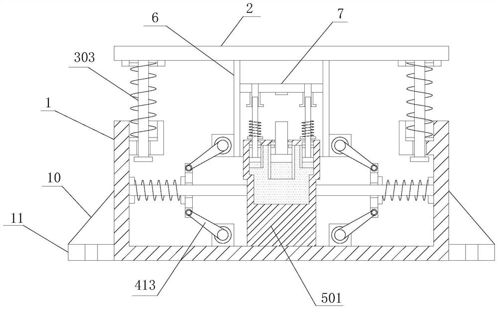
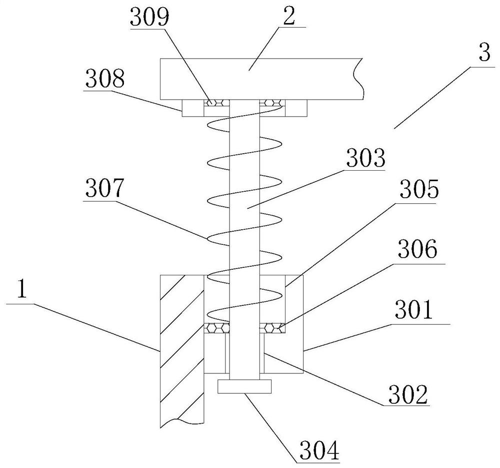
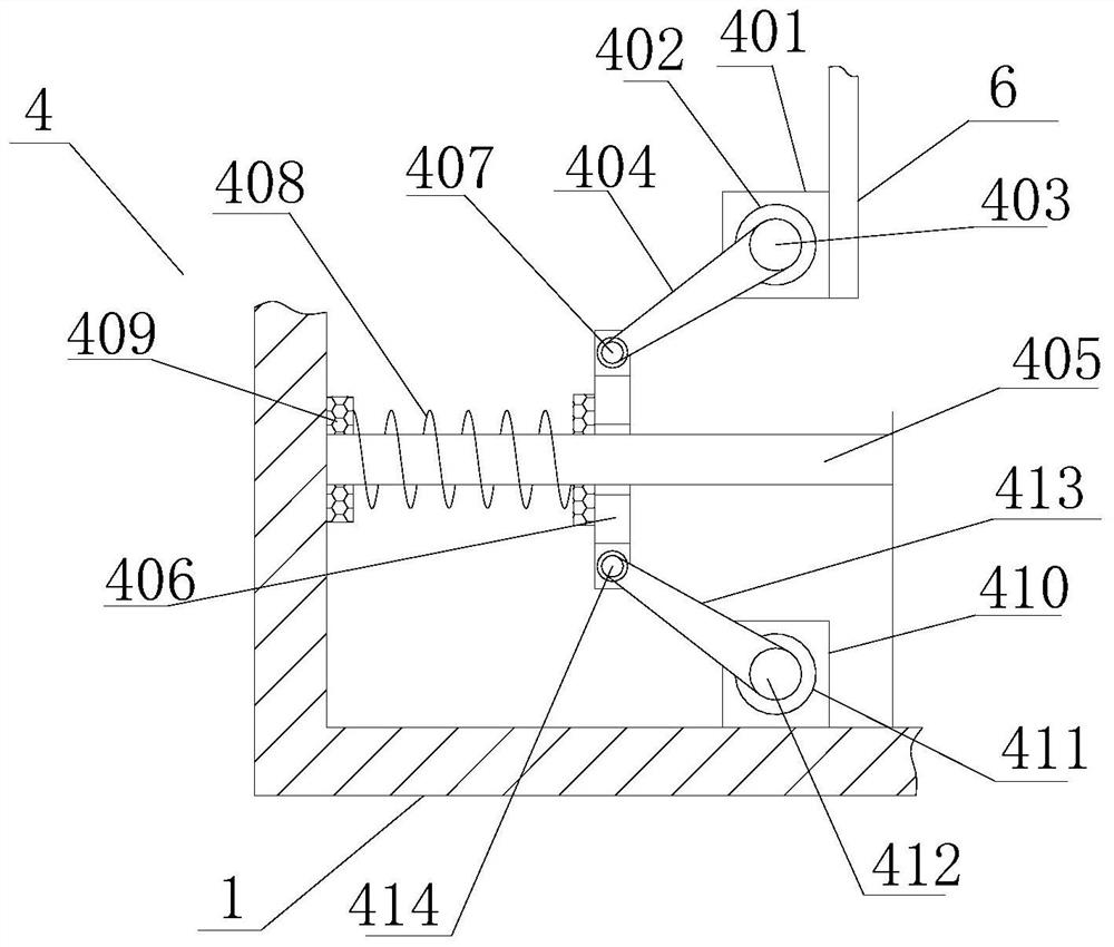
[0028] see Figure 1-7, the present invention provides a technical solution: a mechanical buffer device structure, including a buffer box 1, a receiving plate 2, a first buffer mechanism 3, a second buffer mechanism 4, a third buffer mechanism 5 and a fixed cylinder 6, the body 1 The four corners of the interior are provided with a first buffer mechanism 3, and the top of the buffer box 1 is provided with a receiving plate 2, and the middle part of the bottom ...


PUM


Abstract

The invention relates to the technical field of mechanical buffering, and discloses a mechanical buffering device structure which comprises a buffering box, a bearing plate, first buffering mechanisms, second buffering mechanisms, third buffering mechanisms and a fixing barrel, the first buffering mechanisms are arranged at four corners in a machine body, the bearing plate is arranged above the buffering box, and the fixing barrel is fixedly connected to the middle of the bottom of the bearing plate. According to the mechanical buffering device structure, when the bearing plate is subjected toimpact force, the first buffering mechanisms at the four corners in the buffering box conduct first-step buffering on the bearing plate, and when first buffering springs are extruded by the bearing plate, buffering elastic force is generated to conduct first-step buffering on the impact force on the front face of the bearing plate, then along with downward pressing of the bearing plate, first push rods and second push rods push push plates along second buffering rods to extrude second buffering springs, buffering elastic force is generated to further perform buffering force unloading, the buffering force unloading capacity of a buffering device is improved, and the buffering device is more practical.

Description

technical field [0001] The invention relates to the technical field of mechanical buffering, in particular to a mechanical buffering device structure. Background technique [0002] With the continuous development of industry, more and more mechanical equipment has been developed, and some mechanical power has gradually replaced human labor. Technology is a double-edged sword. In mechanical equipment, many machines have potential safety hazards. If there are no safety protection measures during the movement of mechanical equipment, the strong impact of mechanical equipment will often cause major property damage. Loss and personal injury, the general buffer mechanism, through energy conversion, acts as a mechanism for buffering and shock-absorbing the moving parts of the weapon, and preventing retreat and re-advancement. There are mainly gas buffers with gunpowder gas as the working medium, which are composed of a cylinder, a piston, an air hole, a transmission rod, and an ex...

Claims


Application Information

Patent Timeline
IPC IPC(8): F16F15/02F16F15/023F16F15/08
CPCF16F15/022F16F15/023F16F15/085
Inventor 陈志恒
Owner 德清博发智能科技有限公司
Learn More