
Bidirectional stacked high-current plug terminal and connector with same

A plug-in terminal and high-current technology, which is applied to contact parts and other directions, can solve the problems of poor electrical conductivity, weak current-carrying capacity, and fewer contact points for contact connection, and achieve a small overall structure, increased contact area, and increased The effect of touchpoints

Inactive Publication Date: 2020-12-11
YUEQING BADA OPTICAL ELECTRICAL TECH CO LTD
View PDF10 Cites 1 Cited by
  • Summary
  • Abstract
  • Description
  • Claims
  • Application Information

AI Technical Summary

Problems solved by technology

In the prior art, the plug-in terminal of the connector that uses the socket contact is generally a circular structure. After mating, due to the small contact points and small contact area between the circular-shaped plug-in terminal and the insert piece, resulting in Connectors with the same cross-sectional area have weak current-carrying capacity, high temperature, and poor electrical conductivity
Moreover, the existing circular structure of the plug-in terminal also leads to a larger overall structural size of the connector, which takes up a lot of installation space
In addition, the plug-in terminal with a circular structure, the plug-in piece that matches it, and the connection between the plug-in piece and the cable need to be connected by crimping, resulting in an unreliable connection, low production efficiency, and high cost.
[0003] In addition, most of the existing plug-in terminals adopt shrapnel contact structure. After multi-difference plugging and unplugging, the shrapnel contacts are easy to yield and deform, resulting in fewer contact contacts, which affects the stability and reliability of large current transmission.

Method used


Image

  • Bidirectional stacked high-current plug terminal and connector with same
  • Bidirectional stacked high-current plug terminal and connector with same
  • Bidirectional stacked high-current plug terminal and connector with same

Examples


Embodiment Construction

[0027] The present invention is further described in conjunction with the following examples.

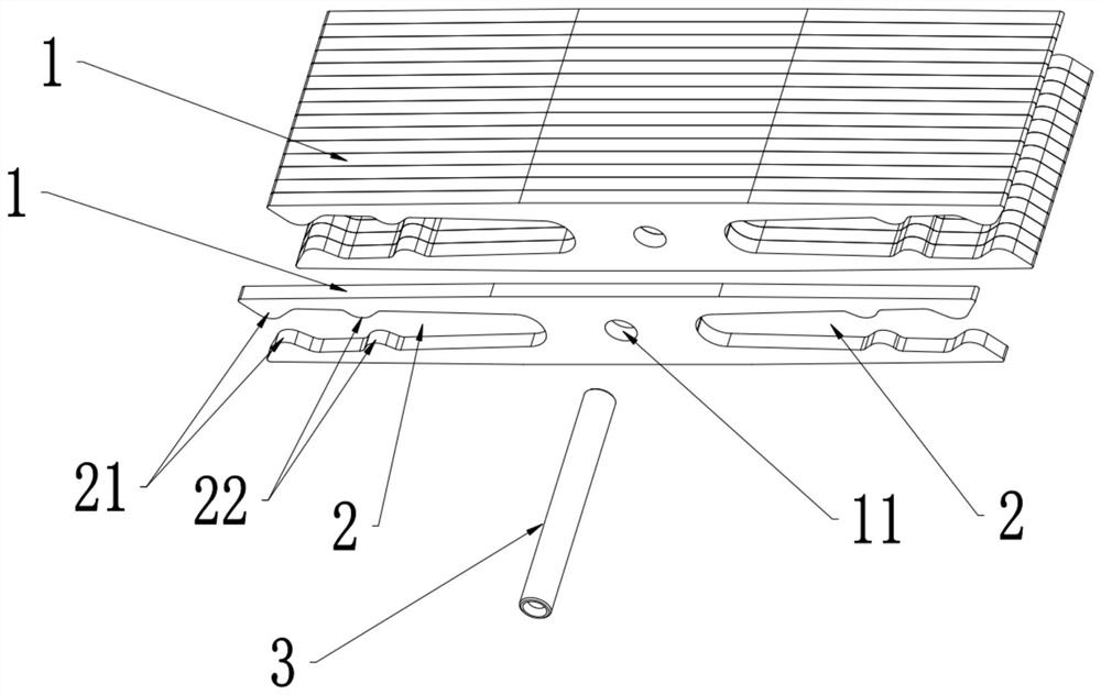
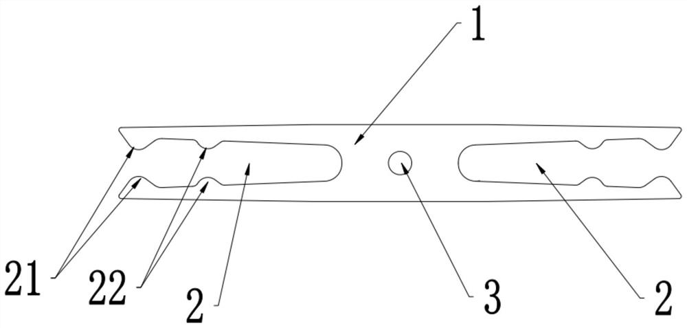
[0028] A specific embodiment of a bidirectional stacked high-current plug-in terminal of the present invention, such as Figure 1-Figure 3 As shown, its structure includes a plurality of terminal grids 1 that are stacked and fixed together, each terminal grid 1 is in the shape of a flat sheet, and each terminal grid 1 is provided with a flat U-shaped plug connector at both ends. Slot 2, the inner side wall of each insertion slot 2 is provided with at least one contact 21, 22 protruding into the slot. . The insertion slot 2 inserts the insert 4, and the contacts 21 and 22 of each insertion slot 2 are in contact with the insert 4, which not only realizes the two-way insertion of the insertion end, but also increases the contact points of the insertion terminal, thereby increasing The large contact area makes the plug terminal have strong current-carrying capacity, low temperature ri...


PUM


Abstract

The invention relates to the technical field of connectors, in particular to a bidirectional stacked high-current plug terminal and a connector, the plug terminal comprises a plurality of terminal grids stacked together, each terminal grid is sheet-shaped, two ends of each terminal grid are provided with flat U-shaped plug slots, and the plug slots are communicated with the plug slots. The inner side wall of each plug slot is provided with at least one contact protruding towards the interior of the slot, a plugging sheet is inserted into the plug slot, and the contact in each plug slot is in contact with the plugging sheet, thereby increasing the number of contact points of the plug terminal, the contact area is increased, and the plug terminal is high in current-carrying capability, low in temperature rise, and good in conductivity. Moreover, the plug terminals with different current-carrying specifications can be formed by adjusting the number of the stacked and fixed terminal grids,thereby meeting different current-carrying capabilities. Besides, the terminal grid is sheet-shaped, so that the overall structure size of the plug terminal is small, and the occupied space is small.The connector with the plug terminal has the characteristics of strong current-carrying capability, low temperature rise and good conductive performance.

Description

technical field [0001] The invention relates to the technical field of connectors, in particular to a bidirectional stacked high-current plug terminal and a connector having the same. Background technique [0002] The plug terminal of the connector is the core component of the connector. In the prior art, the plug-in terminal of the connector that uses the socket contact is generally a circular structure. After mating, due to the small contact points and small contact area between the circular-shaped plug-in terminal and the insert piece, resulting in Connectors with the same cross-sectional area have weak current-carrying capacity, high temperature, and poor electrical conductivity. Moreover, the existing circular-shaped plug-in terminal also leads to a large size of the overall structure of the connector, which takes up a lot of installation space. In addition, the plug-in terminal with a circular structure and the plug-in piece matched with it need to be connected by cr...

Claims


Application Information

Patent Timeline
IPC IPC(8): H01R13/10
CPCH01R13/10
Inventor 陈雪黎欢乐邬其林白志鹏
Owner YUEQING BADA OPTICAL ELECTRICAL TECH CO LTD
Learn More