
Power grid system capable of automatically adjusting voltage fluctuation

A self-adjusting and voltage fluctuation technology, applied in the field of power grid systems, can solve the problems of large size, troublesome operation, inconvenient disassembly work, etc., and achieve the effect of simple and fast operation.

Inactive Publication Date: 2020-12-11
伍保国
View PDF0 Cites 0 Cited by
  • Summary
  • Abstract
  • Description
  • Claims
  • Application Information

AI Technical Summary

Problems solved by technology

[0006] The purpose of the present invention is to provide a power grid system that can self-adjust to voltage fluctuations, so as to solve the problem that the existing power grid systems on the market that can self-adjust to voltage fluctuations proposed by the above-mentioned background technology are relatively large in size, and are difficult to control the entire voltage. The power grid system that adjusts itself to voltage fluctuations needs to be transported and moved using a hoisting device to move the power grid system that self-adjusts to voltage fluctuations to the mobile vehicle, but the power grid system that self-adjusts to voltage fluctuations is inconvenient to install with an external hoisting device. Fixing with ropes is cumbersome to operate. Most of the filter mechanisms in the housing of the existing power grid system that self-adjust to voltage fluctuations are installed and fixed by screws and the housing, so that when the filter mechanism needs to be disassembled, The operation is more troublesome, and it is inconvenient to carry out the disassembly work in the later stage

Method used


Image

  • Power grid system capable of automatically adjusting voltage fluctuation
  • Power grid system capable of automatically adjusting voltage fluctuation
  • Power grid system capable of automatically adjusting voltage fluctuation

Examples


Embodiment Construction

[0029] The following will clearly and completely describe the technical solutions in the embodiments of the present invention with reference to the accompanying drawings in the embodiments of the present invention. Obviously, the described embodiments are only some, not all, embodiments of the present invention. Based on the embodiments of the present invention, all other embodiments obtained by persons of ordinary skill in the art without making creative efforts belong to the protection scope of the present invention.

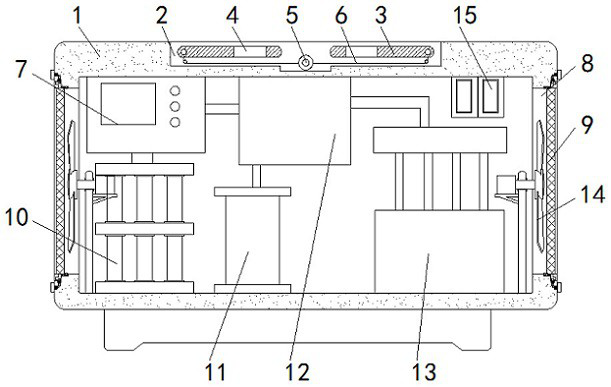
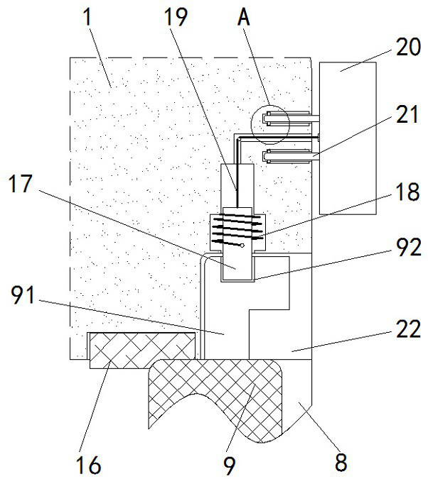
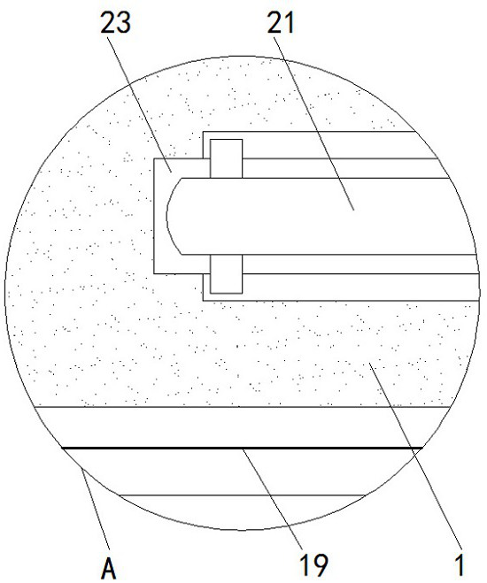
[0030] see Figure 1-8, the present invention provides a technical solution: a power grid system capable of self-adjustment to voltage fluctuations, including a box body 1, a groove 2, a hoisting plate 3, a port 4, a rotating rod 5, a fixed rod 51, a first connection Rope 6, relay 7, air vent 8, filter plate 9, installation block 91, card slot 92, auxiliary transformer 10, main transformer 11, sampling transformer 12, voltage regulator controller 13, heat diss...


PUM


Abstract

The invention discloses a power grid system capable of automatically adjusting voltage fluctuation, which comprises a box main body, a groove, a relay, a sampling transformer and a heat dissipation mechanism, and the groove is formed in the upper surface of the box main body, a rotating rod is placed in the middle of the interior of the groove, and the front end and the rear end of the rotating rod are in bearing connection with the box main body; and adjusting rods are arranged on the left side and the right side of the rotating rod correspondingly, hoisting plates are fixed to the outer sides of the middles of the adjusting rods through screws correspondingly, rope winding discs are in key connection with the outer sides of the rotating rod and the adjusting rods correspondingly, first connecting ropes are fixed to the outer sides of the rope winding discs through winding screws, and one ends of the adjusting rods are connected with the box main body through torsion springs. An auxiliary transformer is installed in the left end of the box main body, and a relay is installed above the auxiliary transformer. According to the power grid system capable of automatically adjusting voltage fluctuation, the two hoisting plates are fixed, and the through holes are formed in the hoisting plates, so that the box main body can be conveniently hoisted and conveyed.

Description

technical field [0001] The invention relates to the technical field of power grid systems, in particular to a power grid system capable of self-adjusting voltage fluctuations. Background technique [0002] With the advent of the power system, the power grid system has also been developed. The power system can be protected through the power grid system, and the stability of the power system transmission can be improved. The power grid system is a public power grid, connected to thousands of various Loads, some of which are large inductive, capacitive, switching power supplies and other loads not only obtain power from the grid, but also affect the grid itself, deteriorating the power supply quality of the grid or local grids, and causing fluctuations in the mains voltage. Therefore, the market There is a power grid system that can automatically adjust to voltage fluctuations, but there are still some shortcomings in the use of existing power grid systems that can automaticall...

Claims


Application Information

Patent Timeline
IPC IPC(8): H02J3/12H02B1/46H02B1/56
CPCH02B1/46H02B1/565H02J3/12
Inventor 不公告发明人
Owner 伍保国
Learn More