Eureka AIR delivers breakthrough ideas for toughest innovation challenges, trusted by R&D personnel around the world.

Switched reluctance driving device with efficient heat dissipation

A switched reluctance drive, high-efficiency technology, applied in the direction of electromechanical devices, cooling/ventilation devices, electric components, etc., can solve the problems of inconvenient disassembly, insufficient protection, weak heat dissipation, etc., to achieve convenient installation and disassembly, strengthen shockproof and safety functions , Strong effect of dustproof function

Inactive Publication Date: 2020-12-11
卞毓平
View PDF6 Cites 2 Cited by
  • Summary
  • Abstract
  • Description
  • Claims
  • Application Information

AI Technical Summary

Problems solved by technology

[0004] The invention provides a high-efficiency heat dissipation switched reluctance driving device, which has the advantages of shock absorption and noise reduction, high-efficiency heat dissipation, more protection and easy disassembly, so as to solve the problems of large noise, weak heat dissipation, insufficient protection and inconvenient disassembly of general devices

Method used


Image

  • Switched reluctance driving device with efficient heat dissipation
  • Switched reluctance driving device with efficient heat dissipation
  • Switched reluctance driving device with efficient heat dissipation

Examples


Embodiment Construction

[0028] The following will clearly and completely describe the technical solutions in the embodiments of the present invention with reference to the accompanying drawings in the embodiments of the present invention. Obviously, the described embodiments are only some, not all, embodiments of the present invention. Based on the embodiments of the present invention, all other embodiments obtained by persons of ordinary skill in the art without making creative efforts belong to the protection scope of the present invention.

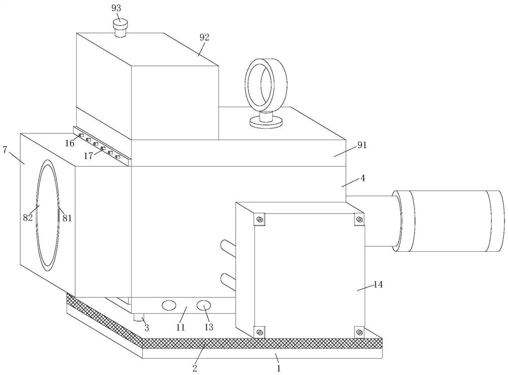
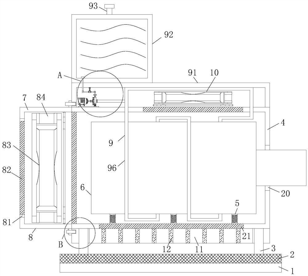
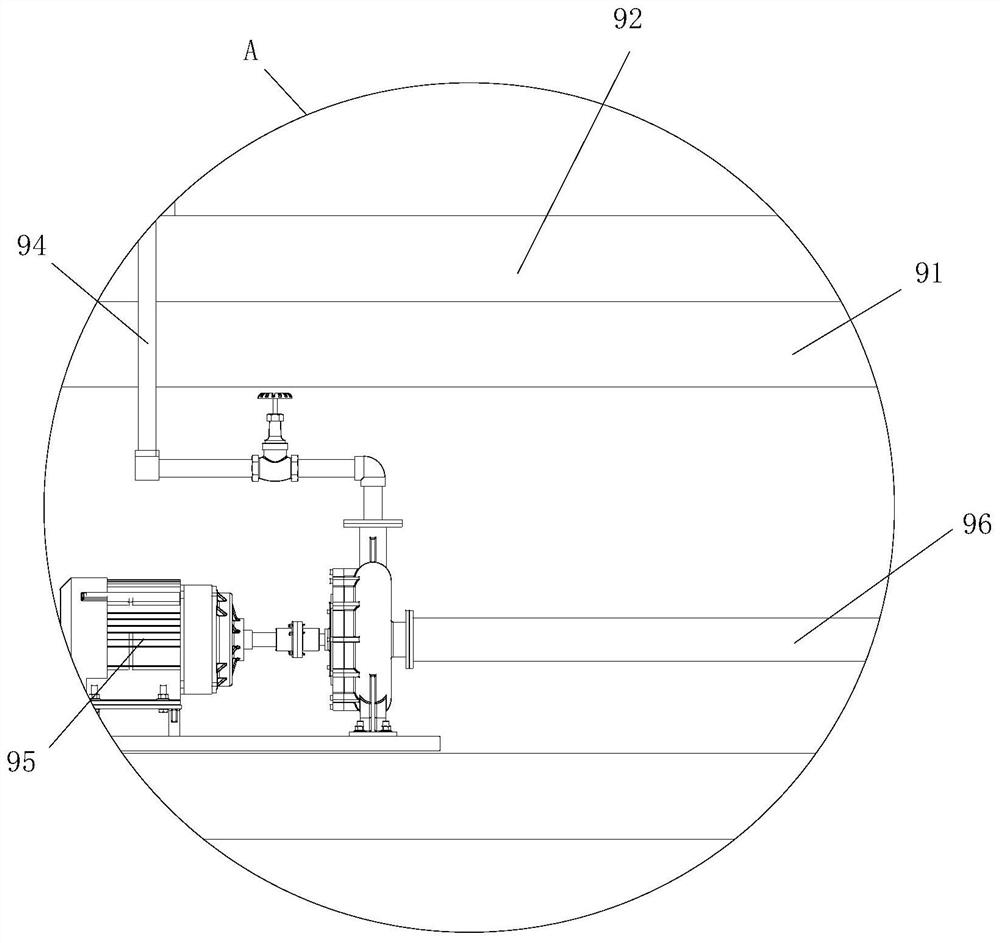
[0029] see Figure 1-5, the present invention discloses a high-efficiency heat dissipation switched reluctance driving device, including a cushion pad 1, a fixed plate 2, a support rod 3, a protective shell 4, a buffer spring 5, a driving motor 6, a ventilation shell 7, and a first ventilation device 8 , water circulation device 9, second ventilation device 10, heat dissipation shell 11, heat dissipation fin 12, heat dissipation hole 13, placement shell 14, fi...


PUM


Abstract

The invention discloses a switched reluctance driving device with efficient heat dissipation, and relates to the technical field of switched reluctance driving. The switched reluctance driving devicewith an efficient heat dissipation function comprises a buffer pad, a fixing plate, a supporting rod, a protective shell, a buffer spring, a driving motor, a ventilation shell, a first ventilation device, a water circulation device, a second ventilation device, heat dissipation shells, cooling fins, heat dissipation holes, a placement shell, fixing grooves, bolts, nuts, a rotor, a stator, positioning holes and a dust filter screen. The number of the heat dissipation holes formed in the front face of the heat dissipation shell is half of the number of the heat dissipation holes formed in the back face of the heat dissipation shell, the heat dissipation function of the device can be improved due to the fact that the heat dissipation holes are formed in the heat dissipation shell, heat can overflow from the lower portion and can also overflow from the front face and the back face of the heat dissipation shell, heat dissipation of the cooling fins is facilitated, the placement shell is arranged at the front surface of the device, in order to avoid temperature rise of the placement shell, no heat dissipation holes are formed in the heat dissipation shell on the back face of the placement shell, the safety performance of the device is improved, and the heat dissipation function is added.

Description

technical field [0001] The invention relates to the technical field of switched reluctance drive, in particular to a high-efficiency heat dissipation switched reluctance drive device. Background technique [0002] Switched reluctance motor is a type of speed-regulating motor developed after DC motor and brushless DC motor. It has been widely used in household appliances, aviation, aerospace, electronics, machinery and electric vehicles. Switched reluctance motor It is a new type of speed regulating motor, which is the latest generation of speed regulating system following frequency conversion speed regulating system and brushless DC motor speed regulating system. It has a simple and firm structure, wide speed regulating range and high system reliability. The complete system mainly includes motor It is composed of entities, power converters, controllers and position detectors. The controller contains the power converter and control circuit, while the rotor position detector ...

Claims


Application Information

Patent Timeline
IPC IPC(8): H02K5/04H02K5/00H02K5/24H02K9/04H02K9/19H02K5/10H02K5/18H02K5/20H02K9/26
CPCH02K5/00H02K5/04H02K5/10H02K5/18H02K5/20H02K5/24H02K9/04H02K9/19H02K9/26
Inventor 卞毓平
Owner 卞毓平
Why Eureka
Eureka Blog
Learn More