Solar outdoor metal flowerpot

A solar energy and metal technology, applied in horticulture, botany equipment and methods, container cultivation, etc., can solve the problems of time-consuming and labor-intensive plant transplanting, consume large plants, and damage the roots of plants, etc., and achieve the effect of convenient and quick transplanting

Inactive Publication Date: 2020-12-15
重庆铝途新型材料有限公司
View PDF9 Cites 0 Cited by
  • Summary
  • Abstract
  • Description
  • Claims
  • Application Information

AI Technical Summary

Problems solved by technology

[0003] The current solar outdoor metal flower pots are widely used, but when transplanting the plants inside the metal flower pots, it often takes a lot of time to lift and pull the plants up, which makes it eas

Method used


Image

  • Solar outdoor metal flowerpot
  • Solar outdoor metal flowerpot
  • Solar outdoor metal flowerpot

Examples


Example Embodiment

[0028] Example 1:

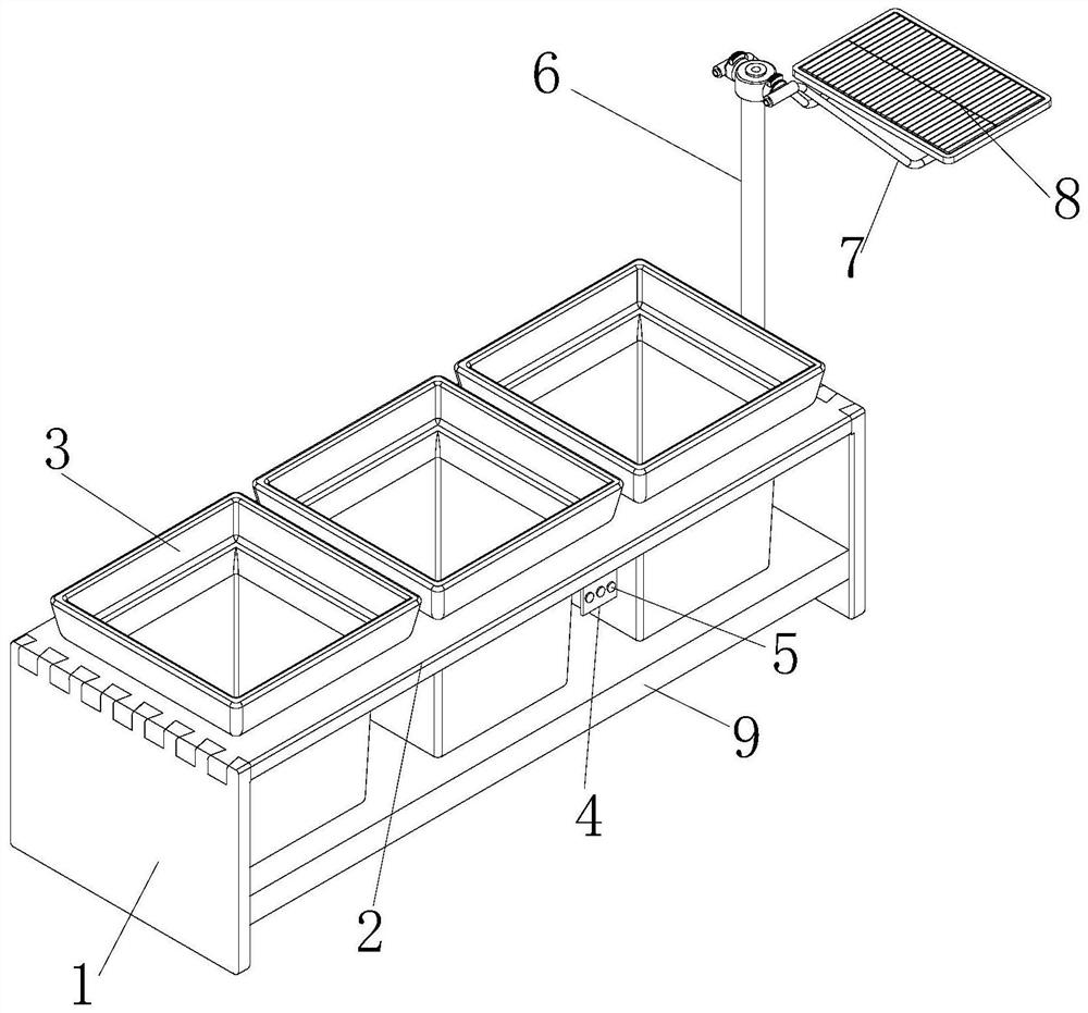
[0029] see figure 1 and figure 2 , the present invention provides a solar outdoor metal flowerpot by improvement, including a support frame 1, a horizontal plate 2, a metal flowerpot body 3, a connection frame 7, a solar cell panel 8 and a top push mechanism 9. The top of the support frame 1 A horizontal plate 2 is provided, the upper end of the horizontal plate 2 is equidistantly distributed with a metal flowerpot body 3, the right end of the horizontal plate 2 is provided with a control panel 4, the upper push mechanism 9 is installed and fixed on the inner lower end of the support frame 1, and the front end of the control panel 4 is installed with a Button 5, the rear end of the support frame 1 is fixed with a vertical rod 6, and the top of the vertical rod 6 is provided with a connecting frame 7, and the connecting frame 7 is fixed with the bottom of the solar cell panel 8.

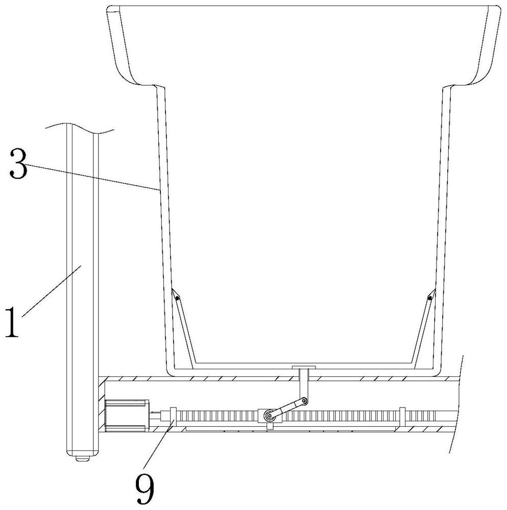
[0030] see image 3 , the present invention provides a solar outdoor metal...

Example Embodiment

[0033] Embodiment 2:

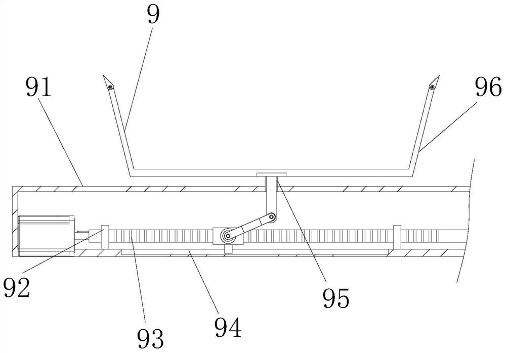
[0034]The present invention provides a solar outdoor metal flowerpot through improvement. There are three metal flowerpot bodies 3 in total, and the metal flowerpot bodies 3 are equally spaced along the horizontal direction of the upper end of the horizontal plate 2. Of course, the metal flowerpot bodies 3 The number can also be set to more, which is not limited here. The slider 934 is in the shape of a cuboid, and the slider 934 is embedded in the inner side of the sliding slot 94, which is beneficial to make the slider 934 move smoothly.

[0035] The present invention provides a solar outdoor metal flowerpot through improvement, and its working principle is as follows;

[0036] First, before use, place the solar outdoor metal flowerpot horizontally, so that the support frame 1 can fix and support the flowerpot;

[0037] Second, when in use, the electric energy generated by the photovoltaic action of the solar cell panel 8 provides power to the motor 9...


PUM


Abstract

The invention discloses a solar outdoor metal flowerpot. The solar outdoor metal flowerpot comprises a supporting frame, a transverse plate, a metal flowerpot body, a connecting frame, a solar cell panel and an upward jacking and pushing mechanism, the upward jacking and pushing mechanism is arranged at the upper end of the supporting frame, an upward moving mechanism drives a bearing frame to move towards the upper end through a push rod; and thereof, plants in a bearing frame move towards the upper end, the plants are higher than the metal flowerpot body, then the plants can be taken down and transplanted, and the advantages that the plants needing to be transplanted can be rapidly jacked upwards and pushed, and transplanting is convenient and rapid are achieved. The upward moving mechanism is arranged at the upper end of the upward jacking and pushing mechanism, a motor is powered on to work, a lead screw is driven to rotate on the inner side of a movable base, and therefore a moving block is driven to move at the right end of the inner side of a sliding groove through a sliding block, the moving block drives a push rod to move towards the upper end through a swing rod, and thebearing frame is pushed towards the upper end; and the advantage that the bearing frame can be quickly pushed to the upper end is achieved.

Description

technical field [0001] The invention relates to the related field of metal flower pots, in particular to a solar outdoor metal flower pot. Background technique [0002] A flower pot, a vessel used for planting flowers, is in the shape of a rounded or chamfered table with a large mouth and a small bottom. The flower pots for planting flowers are in various forms and sizes. Flower producers or flower growers can choose flower pots according to the characteristics and needs of flowers and the characteristics of flower pots. According to different materials, they can be divided into many types. [0003] The current solar outdoor metal flower pots are widely used, but when transplanting the plants inside the metal flower pots, it often takes a lot of time to lift and pull the plants up, which makes it easy to damage the roots of the plants. The existing solar outdoor Metal flower pots are not easy to quickly push up the plants that need to be transplanted, which makes plant tra...

Claims


Application Information

Patent Timeline
IPC IPC(8): A01G9/02
CPCA01G9/02
Inventor 饶承于
Owner 重庆铝途新型材料有限公司
Why Eureka
Try Eureka