Automatic ventilation device of greenhouse and greenhouse

A technology for a ventilation device and a greenhouse, which is applied in the field of greenhouses, can solve the problems of high cost, inconvenient cost, and poor reliability of the control device, and achieves the effects of low cost, convenient use and good ventilation effect.

Active Publication Date: 2020-12-15
NINGBO UNIVERSITY OF TECHNOLOGY
View PDF4 Cites 2 Cited by
  • Summary
  • Abstract
  • Description
  • Claims
  • Application Information

AI Technical Summary

Problems solved by technology

Especially in the hot summer, if there is no ventilation, strong solar radiation and greenhouse effect will not only make it difficult for crops to grow, but also a great physiological limit test for the staff in the greenhouse
[0003] In the existing greenhouse ventilation device design, the traditional solution is to control the opening and closing of the greenhouse window by controlling the positive and negative rotation of the motor, but there are the following disadvantages: (1) A power supply system is required, which is not suitable for some outdoor greenhouse environments. Inconvenient or high cost; (2) no energy-saving advantages; (3) poor reliability, the high temperature and humidity environment in the field or in the greenhouse is not conducive to the use of electronic control; (4) the cost of the entire control device is too high, and there is no promotion value
But the automatic ventilation device of this existing greenhouse still has the following technical problems: since the shape-memory alloy is directly connected with the skylight and driven, where the skylight is arranged, the shape-memory alloy is just arranged there; Finally, the cool wind entering from the outside will first lower the temperature of the local area near the skylight, so that the shape memory alloy will sense the temperature drop, and will be deformed to close the skylight, but in fact the overall temperature of the greenhouse has not changed at all. decline, making it difficult to achieve the desired ventilation effect

Method used


Image

  • Automatic ventilation device of greenhouse and greenhouse
  • Automatic ventilation device of greenhouse and greenhouse
  • Automatic ventilation device of greenhouse and greenhouse

Examples


Embodiment Construction

[0041] The following are specific embodiments of the present invention and in conjunction with the accompanying drawings, the technical solutions of the present invention are further described, but the present invention is not limited to these embodiments.

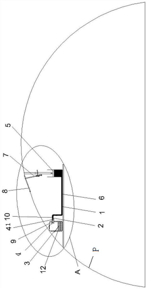
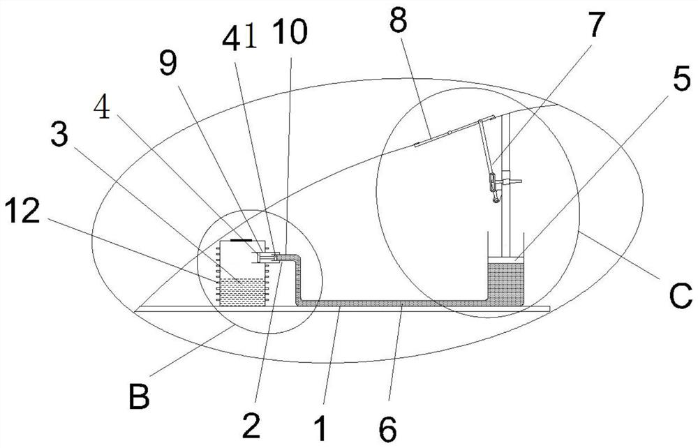
[0042] Such as Figure 1-11 Shown, a kind of automatic ventilation device of greenhouse includes:

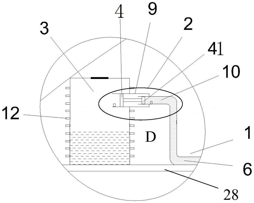
[0043] A container with a closed chamber (not marked in the figure); the container is provided with a joint 9 communicating with the closed chamber, and the first fluid 3 is provided in the closed chamber; wherein, as image 3 As shown, a liquid injection port can also be set on the top of the container, and a detachable sealing plate is arranged at the liquid injection port. The liquid injection port is convenient for injecting the first fluid 3 into the container. Fix the sealing plate on the container to ensure the airtightness of the container.

[0044] The connecting pipe 1 is a U-shaped pipe. In this solution, the co...


PUM


Abstract

The invention relates to the technical field of greenhouses, and discloses an automatic ventilation device of a greenhouse and the greenhouse. The automatic ventilation device comprises a container with a closed cavity, a connecting pipe and a transmission mechanism; the container is provided with a connector communicated with the closed cavity, and first fluid is arranged in the closed cavity ; the connecting pipe is communicated with the connector, a first piston is arranged at the end, close to the connector, of the connecting pipe and / or in the connector, and second fluid is arranged in the connecting pipe; the transmission mechanism is used for driving a skylight and comprises a second piston, the second piston is arranged at the other end of the connecting pipe, and second fluid is located between the first piston and the second piston; and when the pressure in the closed chamber changes, the second piston can be driven by the first piston and the second fluid. The automatic ventilation device has the advantages that electric drive is not needed for the automatic ventilation device, the temperature in the greenhouse can be correctly sensed, the ventilation effect is good, thewindow opening sensitivity is adjustable, and the application range is wide.

Description

technical field [0001] The invention relates to the technical field of greenhouses, in particular to an automatic ventilation device for a greenhouse and a greenhouse. Background technique [0002] Greenhouses need frequent ventilation, which has beneficial effects on cooling vegetables and plants in greenhouses, dehumidifying, regulating and replenishing carbon dioxide, and eliminating harmful gases. Especially in hot summer, if there is no ventilation, strong solar radiation and greenhouse effect will not only make it difficult for crops to grow, but also a great physiological limit test for the staff in the greenhouse. [0003] In the existing greenhouse ventilation device design, the traditional solution is to control the opening and closing of the greenhouse window by controlling the positive and negative rotation of the motor, but there are the following disadvantages: (1) It requires a power supply system, which is not suitable for some outdoor greenhouse environments...

Claims


Application Information

Patent Timeline
Patent Type & Authority Applications(China)
IPC IPC(8): A01G9/14A01G9/24
CPCA01G9/14A01G9/241A01G9/246Y02A40/25
Inventor 李昌刚陈晓平王涛
Owner NINGBO UNIVERSITY OF TECHNOLOGY
Why Eureka
Try Eureka