Supercharge Your Innovation With Domain-Expert AI Agents!

Metal waste crushing and recycling device

A recovery device and waste technology, which is applied in the field of metal waste crushing and recycling devices, can solve the problems of insufficient fineness, material jamming and crushing, etc., and achieve the effect of thorough crushing and slow down the falling speed

Inactive Publication Date: 2020-12-15
邱洁
View PDF0 Cites 0 Cited by
  • Summary
  • Abstract
  • Description
  • Claims
  • Application Information

AI Technical Summary

Problems solved by technology

[0004] Based on the technical problems that the existing metal waste crushing and recycling device is easy to get stuck and the crushing is not fine enough, the present invention proposes a metal waste crushing and recycling device

Method used


Image

  • Metal waste crushing and recycling device
  • Metal waste crushing and recycling device
  • Metal waste crushing and recycling device

Examples


Embodiment 1

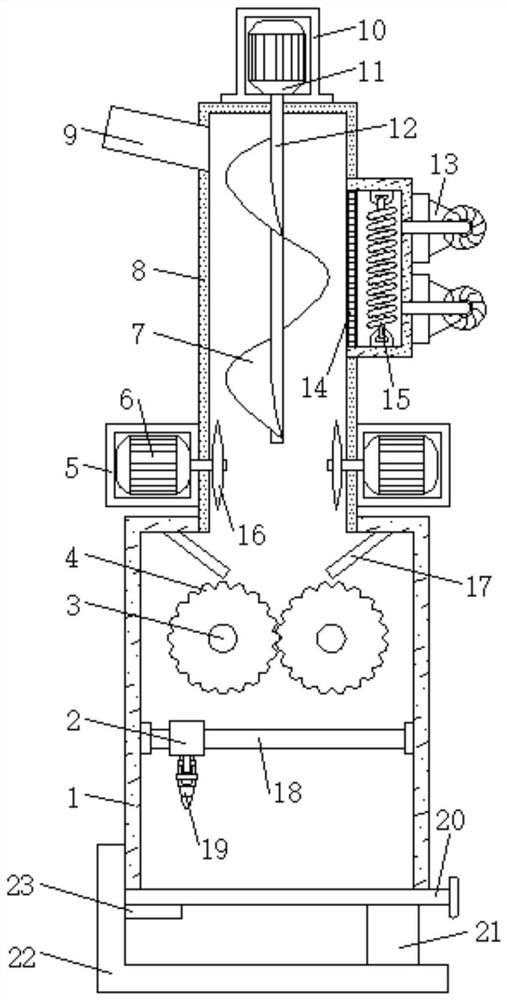
[0025] refer to Figure 1-3 , a metal waste crushing and recycling device, comprising a crushing box 1, a feeding box 8 is inserted in the middle of the outer wall of the top of the crushing box 1, and a feeding hopper 9 is inserted in a position close to the top of one side of the outer wall of the feeding box 8. The top outer wall of the box 8 is fixed with a motor frame 10 by bolts, the bottom inner wall of the motor frame 10 is provided with a first motor 11, and one end of the output shaft of the first motor 11 is keyed to a drive shaft 12, and one end of the drive shaft 12 is located at the feeding Inside the box 8, a screw feeding tray 7 is fixedly connected to the peripheral outer wall of the transmission shaft 12, a drying mechanism is provided on one side of the outer wall of the feeding box 8, and a cutting mechanism is provided on the outer wall of the feeding box 8 on both sides close to the crushing box 1. The outer wall of one side of the crushing box 1 near the...

Embodiment 2

[0029] refer to Figure 4, a metal waste crushing and recycling device. Compared with Embodiment 1, this embodiment has a smoke concentration sensor 30 fixed on one side of the crushing box 1 by bolts, and an alarm sensor 30 is fixed on one side of the crushing box 1 on the outer wall by bolts. 31, the signal output end of the smoke concentration sensor 30 is connected to the signal input end of the alarm 31 through a signal line.

[0030] During use, the interior of the crushing box 1 is provided with a smoke concentration sensor 30, which can detect the smoke concentration inside the crushing box 1. It is provided with a high critical value. When the relatively large smoke generated inside the crushing box 1 reaches the high critical value, a signal will be output To the alarm 31, thereby causing the alarm 31 to report to the police, reminding the staff to come and deal with it, so as to avoid further expansion of the problem.


PUM


Abstract

The invention discloses a metal waste crushing and recycling device, and aims at solving the problems that materials are prone to blockage and crushing is not fine enough during crushing. According tothe following scheme, the metal waste crushing and recycling device comprises a crushing box, wherein a feeding box is inserted in the middle of the outer wall of the top of the crushing box; a feedhopper is inserted in the position, close to the top, of the outer wall of one side of the feeding box; a motor frame is fixed to the outer wall of the top of the feeding box through bolts; a first motor is arranged on the inner wall of the bottom of the motor frame; one end of an output shaft of the first motor is in key connection with a transmission shaft; one end of the transmission shaft is located in the feeding box; and a spiral feeding disc is fixedly connected to the circumferential outer wall of the transmission shaft. According to the metal waste crushing and recycling device, the metal waste is slowly conveyed and the discharging speed is decreased, so that crushing can be conducted more thoroughly; and a second motor drives linear cutting blades to conduct rapid cutting at thetail end of the spiral feeding disc, a hernia lamp serves as an excitation source, so that secondary cutting is achieved, and thus the metal waste is crushed more thoroughly.

Description

technical field [0001] The invention relates to the technical field of recycling devices, in particular to a metal waste crushing and recycling device. Background technique [0002] Metal waste refers to non-metal. Scrap metal refers to metal fragments and scraps discarded by the metallurgical industry and metal processing industry, as well as metal utensils discarded by equipment renewal, etc., and also includes metal objects such as metal packaging containers and waste vehicles recovered from urban garbage. , Metal waste usually needs to be crushed and recycled, so it is necessary to use a metal waste crushing and recycling device. [0003] Most of the existing metal waste crushing and recycling device patents on the market have the following deficiencies: the material is easy to get stuck and the crushing is not fine enough, and the existing patents are not easy to solve such problems. Therefore, there is an urgent need for a metal waste crushing and recycling device. Th...

Claims


Application Information

Patent Timeline
IPC IPC(8): B02C4/08B02C4/42B23K26/38B02C23/02
CPCB02C4/08B02C4/286B02C4/42B23K26/38
Inventor 邱洁
Owner 邱洁
Features
  • R&D
  • Intellectual Property
  • Life Sciences
  • Materials
  • Tech Scout
  • Unparalleled Data Quality
  • Higher Quality Content
  • 60% Fewer Hallucinations
Learn More