
Linear correction method, laser marking equipment and storage medium

A linear correction and laser marking technology, which is applied in the field of laser applications, can solve the problems of large-format platform marking loss accuracy, etc., and achieve the effect of improving the correction speed and marking accuracy

Active Publication Date: 2020-12-15
SHENZHEN TETELASER TECH CO LTD
View PDF6 Cites 0 Cited by
  • Summary
  • Abstract
  • Description
  • Claims
  • Application Information

AI Technical Summary

Problems solved by technology

With the continuous increase of the marking format, the range of the scanning galvanometer cannot meet the one-time marking requirements, and the XY motion table has become a necessary accessory, and the worktable and the scanning galvanometer will naturally have an angle during the assembly process. If If the angle correction between the worktable and the scanning galvanometer is not performed, the large-format platform marking will lose accuracy

Method used

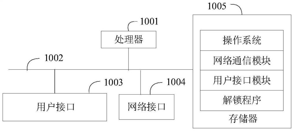
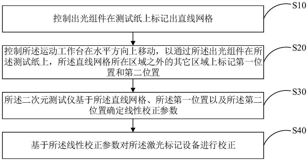
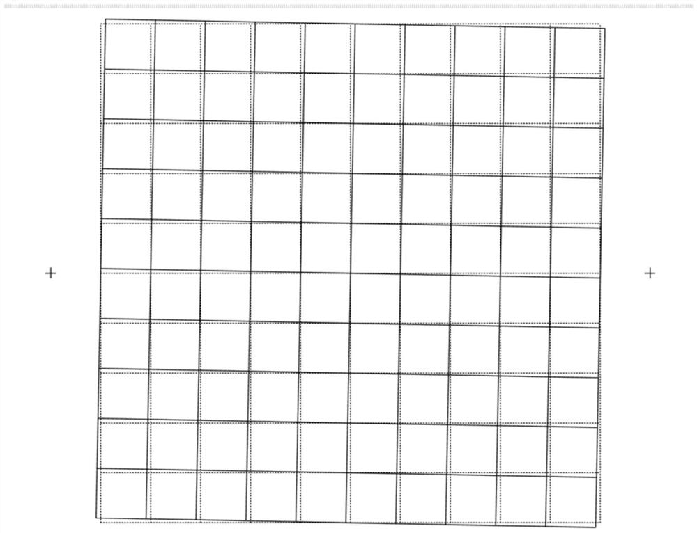

Image

  • Linear correction method, laser marking equipment and storage medium
  • Linear correction method, laser marking equipment and storage medium
  • Linear correction method, laser marking equipment and storage medium

Examples


Embodiment Construction

[0036] It should be understood that the specific embodiments described here are only used to explain the present invention, not to limit the present invention.

[0037] With the diversification of market demand, laser marking technology is also constantly innovating and developing. With the continuous increase of the marking format, the range of the scanning galvanometer cannot meet the one-time marking requirements, and the XY motion table has become a necessary accessory, and the worktable and the scanning galvanometer will naturally have an angle during the assembly process. If If the angle correction between the worktable and the scanning galvanometer is not carried out, the large-format platform marking will lose accuracy.

[0038] In order to improve the accuracy of laser marking equipment, an embodiment of the present invention proposes a linear correction method, the main solution of which includes the following steps:

[0039] Control the light-emitting component to ...


PUM


Abstract

The invention discloses a linear correction method. The linear correction method comprises the following steps of: controlling a light emitting component to mark linear grids on test paper; controlling a moving workbench to move in the horizontal direction so as to mark a first position and a second position on the test paper and other areas excluding the area where the linear grids are located bythe light emitting component; using a quadratic tester to determine linear correction parameters based on the linear grids, the first position and the second position; and correcting the laser marking equipment based on the linear correction parameters. The invention further discloses laser marking equipment and a computer readable storage medium, which achieve the effect of improving the precision of the laser marking equipment.

Description

technical field [0001] The invention relates to the technical field of laser applications, in particular to a linear correction method, a laser marking device and a computer-readable storage medium. Background technique [0002] With the diversification of market demand, laser marking technology is also constantly innovating and developing. With the continuous increase of the marking format, the range of the scanning galvanometer cannot meet the one-time marking requirements, and the XY motion table has become a necessary accessory, and the worktable and the scanning galvanometer will naturally have an angle during the assembly process. If If the angle correction between the worktable and the scanning galvanometer is not carried out, the large-format platform marking will lose accuracy. [0003] The above content is only used to assist in understanding the technical solution of the present invention, and does not mean that the above content is admitted as prior art. Conte...

Claims


Application Information

Patent Timeline
IPC IPC(8): B23K26/362B23K26/70
CPCB23K26/362B23K26/702
Inventor 王双贾长桥周红林盛辉张凯
Owner SHENZHEN TETELASER TECH CO LTD
Learn More