Bridge floor concrete layer reinforcing steel bar positioning device

A positioning device and concrete layer technology, which is applied in bridges, bridge construction, erection/assembly of bridges, etc., can solve the problems of poor marking accuracy, great influence on surface flatness, inconvenient control and adjustment of spacing, etc., to avoid impact, Easy-to-promote, ingeniously structured effects

Active Publication Date: 2020-01-17
HENAN UNIV OF URBAN CONSTR
View PDF28 Cites 0 Cited by
  • Summary
  • Abstract
  • Description
  • Claims
  • Application Information

AI Technical Summary

Problems solved by technology

[0006] In view of the above situation, in order to overcome the defects of the prior art, the present invention provides a positioning device for steel bars on the concrete layer of the bridge deck, which effectively solves the problem of poor marking accuracy when laying steel bars in the prior art, inconvenient control and adjustment of the spacing, and is affected by the ground surface. Problems with greater impact on flatness

Method used


Image

  • Bridge floor concrete layer reinforcing steel bar positioning device
  • Bridge floor concrete layer reinforcing steel bar positioning device
  • Bridge floor concrete layer reinforcing steel bar positioning device

Examples


Embodiment Construction

[0021] The specific implementation manners of the present invention will be further described in detail below in conjunction with the accompanying drawings.

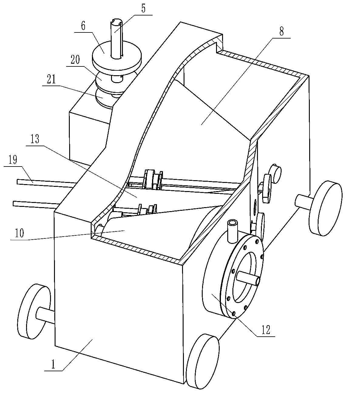
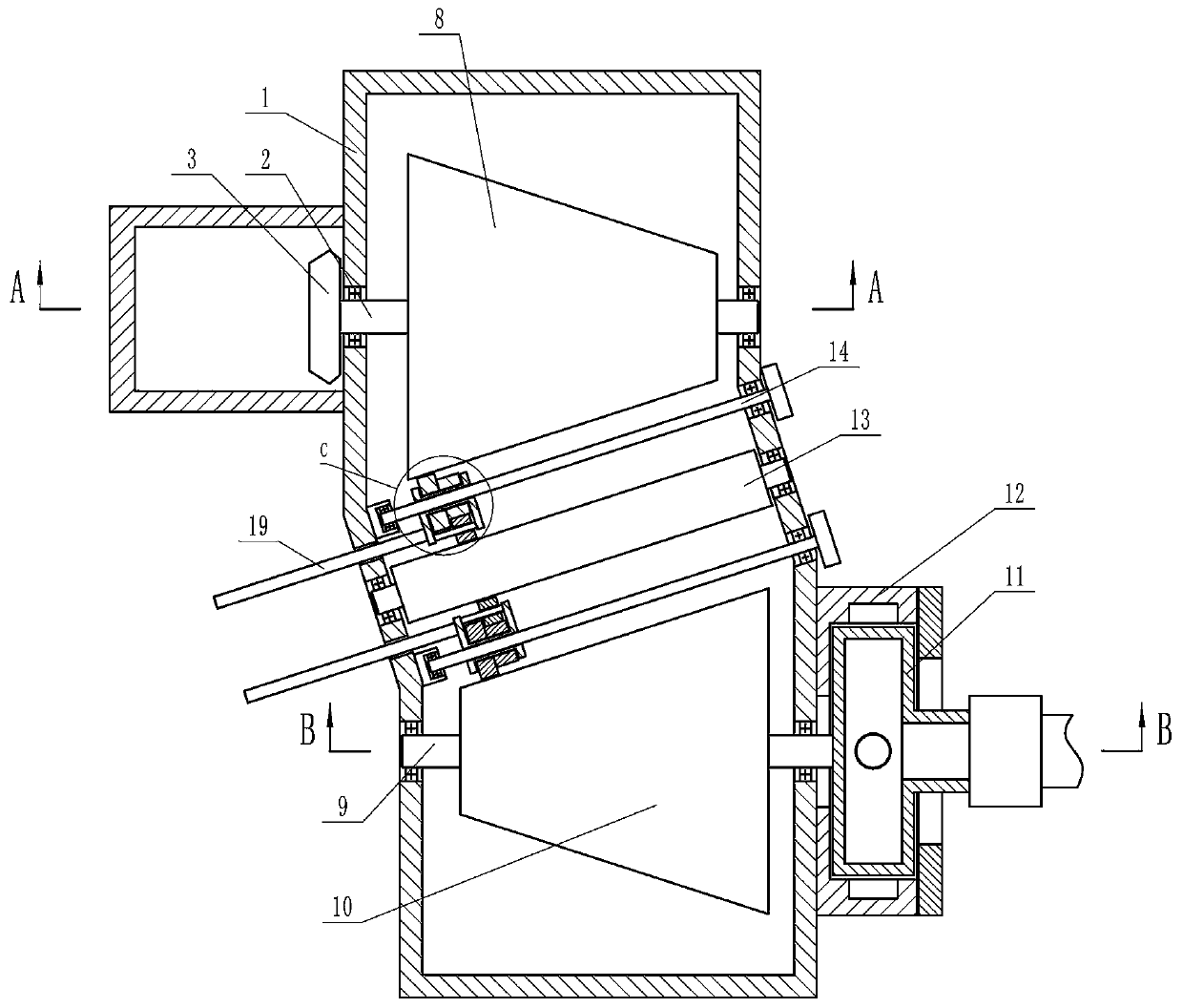
[0022] Depend on Figure 1 to Figure 11 Given, the present invention includes a rectangular housing 1. There is a horizontal and rotatable driving shaft 2 inside the housing 1. The left end of the driving shaft 2 passes through the side wall of the housing 1 and is placed outside the housing 1. The left end of the driving shaft 2 is fixed with a The first bevel gear 3, the upper side of the first bevel gear 3 is meshed with a horizontal second bevel gear 4, the upper end of the central axis of the first bevel gear 3 is connected with a spline shaft 5 through a universal coupling, the spline shaft 5 The upper sleeve is equipped with a roller 6 that can move up and down along the spline shaft 5. A slideway 7 parallel to the ground is arranged on one side of the housing 1. The roller 6 can roll along the slideway, and the r...


PUM


Abstract

The invention provides a bridge floor concrete layer reinforcing steel bar positioning device which effectively solves the problems that in the prior art, when the reinforcing steel bars are laid, themarking precision is poor, the distance is inconvenient to control and adjust, and the influence of the ground surface flatness is larger. According to the technical scheme, the device comprises a rectangular shell, a driving shaft is arranged in the shell, and a first bevel gear is arranged at the left end of the driving shaft; a second bevel gear is meshed with the upper side of the first bevelgear, the upper end of a center shaft of the first bevel gear is connected with a spline shaft through a universal coupling, and a roller sleeves the spline shaft; a sliding way is arranged at one side of the shell, a driving wheel is fixed to the driving shaft, and a driven shaft is arranged at the front side of the driving shaft and is provided with a driven wheel; a transmission device is installed between the driven wheel and the driving wheel, a cylindrical shell is fixed to the right end of the driven shaft, and coating is arranged in the cylindrical shell; a discharging hole is formedon the side wall of the cylindrical shell, an annular block sleeves the outer side of the cylindrical shell and is fixed to the shell, and vertical through holes are formed on the side walls of the upper end and the lower end of the annular block.

Description

technical field [0001] The invention relates to the technical field of steel bar positioning, in particular to a steel bar positioning device for a bridge deck concrete layer. Background technique [0002] At present, in the municipal construction, the distance between road and bridge reinforcing bars is generally all manually marked or set out by workers with a scale in the prior art. In this way, manual marking often leads to large errors, resulting in unbalanced forces in local areas, which not only affects the quality of the project, but also affects the progress of the construction and increases the construction cost. [0003] In the prior art, the patent document with application number 201310084749.4 discloses a steel bar spacing marker for building construction, in order to solve the problems of large randomness and insufficient precision in manual marking. It uses the rotation of the wheel to drive the rotation of the spokes. During the rotation, the spokes first p...

Claims


Application Information

Patent Timeline
IPC IPC(8): E01D21/00
CPCE01D21/00
Inventor 夏英志黄艳娜刘英强曹淞涛王晓宇彭海洋张晓鹏
Owner HENAN UNIV OF URBAN CONSTR
Why Eureka
Try Eureka