Steel bar spacing marking device

A technology for the spacing and punctuation of rebars, which is applied in the field of punctuation devices for rebar spacing, can solve the problems of large influence of surface flatness, poor marking accuracy, inconvenient control and adjustment of spacing, etc. Effect

Active Publication Date: 2020-01-17
四川省佳宇建设集团有限公司
View PDF24 Cites 0 Cited by
  • Summary
  • Abstract
  • Description
  • Claims
  • Application Information

AI Technical Summary

Problems solved by technology

[0006] In view of the above situation, in order to overcome the defects of the prior art, the present invention provides a steel bar spacing punctuation device, which effectively solves the problem of poor marking accuracy when laying steel bars in the prior art, inconvenient control and adjustment of the spacing, and is affected by the flatness of the ground surface. bigger problem

Method used


Image

  • Steel bar spacing marking device
  • Steel bar spacing marking device
  • Steel bar spacing marking device

Examples


Embodiment Construction

[0017] The specific implementation manners of the present invention will be further described in detail below in conjunction with the accompanying drawings.

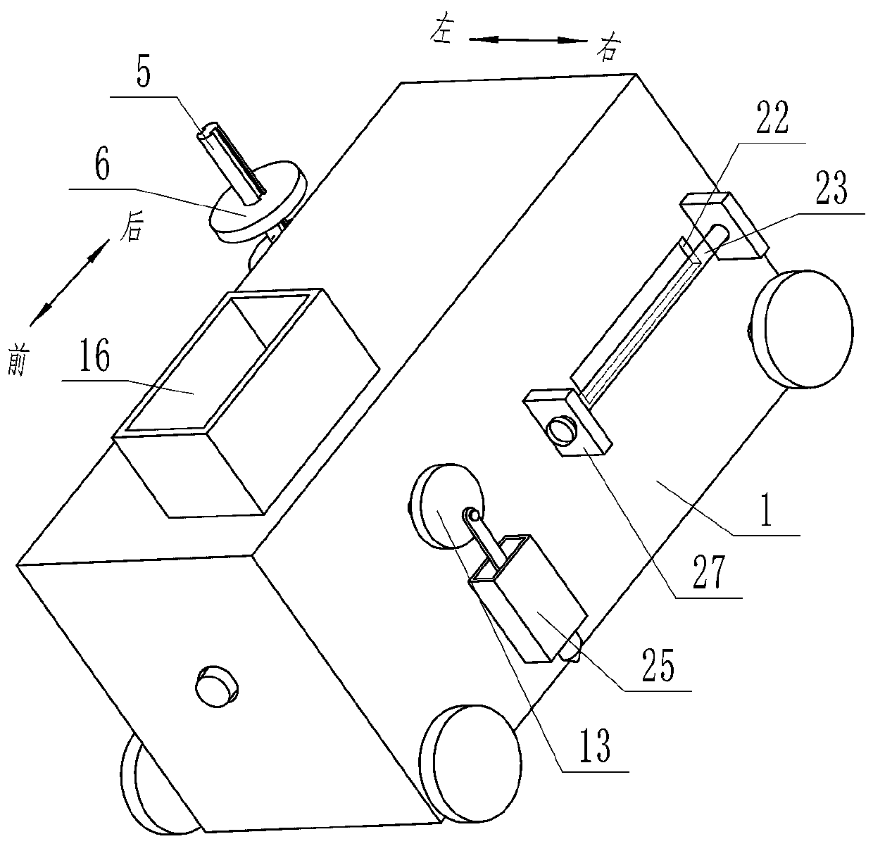
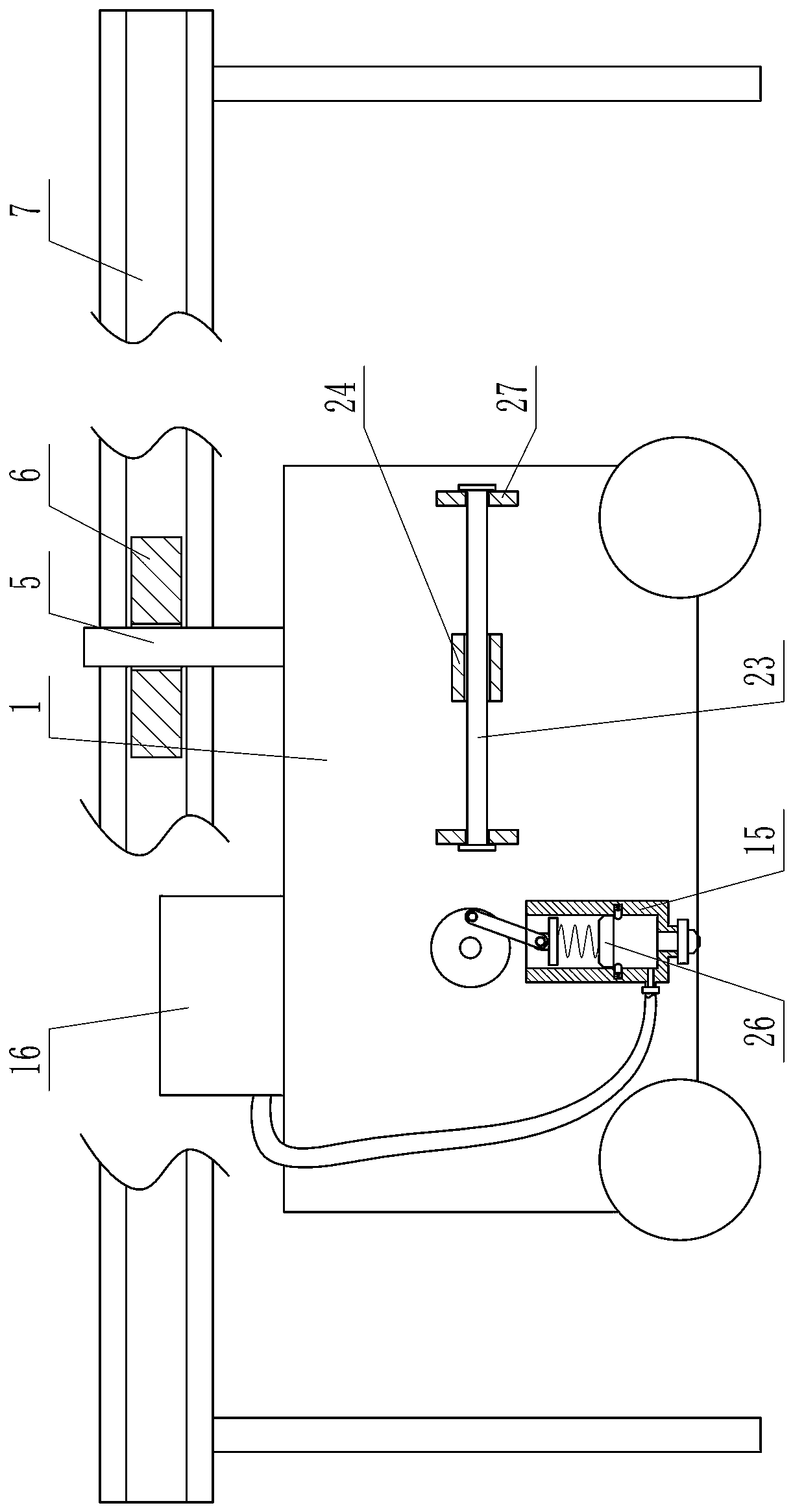
[0018] Depend on Figure 1 to Figure 8 Given, the present invention includes a rectangular housing 1, a horizontal drive shaft 2 that can actively rotate runs through the left side wall of the housing 1, the left end of the driving shaft 2 penetrates the side wall of the housing 1 and is placed outside the housing 1, the active The left end of the shaft 2 is fixed with the first bevel gear 3, the upper side of the first bevel gear 3 is meshed with the horizontal second bevel gear 4, and the upper end of the central axis of the first bevel gear 3 is connected with a spline shaft 5 through a universal coupling , the spline shaft 5 is set with a roller 6 that can move up and down along the spline shaft 5, a slideway 7 parallel to the ground is arranged on one side of the housing 1, the roller 6 can roll along the slideway 7...


PUM


Abstract

The invention provides a steel bar spacing marking device which effectively solves the problems that in the prior art, when the steel bars are laid, the marking precision is poor, the spacing size isinconvenient to control and adjust, and the influence of the ground surface flatness is larger. According to the technical scheme, the device comprises a rectangular shell, a driving shaft penetratesthrough the left side wall of the shell, and a first bevel gear is arranged at the left end of the driving shaft. The upper side of the first bevel gear is meshed with a second bevel gear, the upper end of a center shaft of the first bevel gear is connected with a spline shaft through a universal coupling, and a roller sleeves the spline shaft. A slideway is arranged at one side of the shell, a longitudinal shaft is arranged in the shell and is equipped with a driving wheel, and a first friction disc is arranged at the left side of the driving wheel. A second friction disc is arranged at the right side of the driving wheel, a driven shaft penetrates through the right side plate of the shell, and a cam disc is arranged at the right end of a driven shaft. A connecting rod is connected to thecam disc, a piston cylinder is fixed to the outer side of the right side plate of the shell, the lower end of the connecting rod is hinged to a piston to form a slider-crank mechanism, and a materialstorage box is fixed to the upper end of the shell.

Description

technical field [0001] The invention relates to the technical field of steel bar positioning, in particular to a steel bar spacing marking device. Background technique [0002] At present, in the municipal construction, the distance between road and bridge reinforcing bars is generally all manually marked or set out by workers with a scale in the prior art. In this way, manual marking often leads to large errors, resulting in unbalanced forces in local areas, which not only affects the quality of the project, but also affects the progress of the construction and increases the construction cost. [0003] In the prior art, the patent document with application number 201310084749.4 discloses a steel bar spacing marker for building construction, in order to solve the problems of large randomness and insufficient precision in manual marking. It uses the rotation of the wheel to drive the rotation of the spokes. During the rotation, the spokes first pass through the ink-soaked co...

Claims


Application Information

Patent Timeline
IPC IPC(8): E01D21/00E04G21/18
CPCE01D21/00E04G21/1841
Inventor 夏英志黄艳娜刘英强曹淞涛王晓宇彭海洋张晓鹏
Owner 四川省佳宇建设集团有限公司
Why Eureka
Try Eureka