Shirt collar type mold machine with multi-directional core pulling mechanism and implementation method thereof

A core-pulling mechanism and multi-directional technology, applied in the field of mold machines, can solve the problems of easy-to-adhesion injection molding parts, many core-pulling mechanisms, and poor use effect, and achieve the effect of convenient storage.

Pending Publication Date: 2020-12-15
河北万发服装纺织集团有限公司
View PDF0 Cites 3 Cited by
  • Summary
  • Abstract
  • Description
  • Claims
  • Application Information

AI Technical Summary

Problems solved by technology

[0003] However, the core-pulling mechanism of the mold machine is driven by an oil cylinder to complete the core-pulling. During the process of core-pulling, the outer surface is easy to stick to the injection molded parts, which is inconvenient to clean. Moreover, there are many core-pulling mechanisms, and the production cost is also high. The requirements for the mold are high. Bad use

Method used


Image

  • Shirt collar type mold machine with multi-directional core pulling mechanism and implementation method thereof
  • Shirt collar type mold machine with multi-directional core pulling mechanism and implementation method thereof
  • Shirt collar type mold machine with multi-directional core pulling mechanism and implementation method thereof

Examples


Embodiment 1

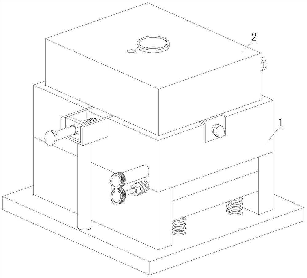
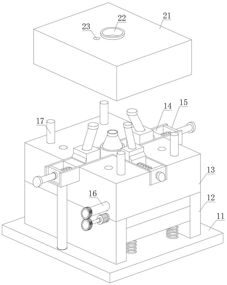
[0037] see figure 1 , figure 2 and image 3, a shirt collar mold machine with a multi-directional core-pulling mechanism, comprising a lower mold 1 and an upper mold 2, the upper mold 2 is movably installed on the upper end of the lower mold 1, and the lower mold 1 includes a base 11, a support 12, and a mold base 13 , Groove 14, upper core-pulling mechanism 15, lower core-pulling mechanism 16 and positioning column 17, the support 12 is arranged on the upper end of the base 11, the mold base 13 is fixedly installed on the upper end of the support 12, and the groove 14 is arranged on the mold base 13, there are three groups of upper core-pulling mechanisms 15, and the upper core-pulling mechanisms 15 of the three groups are all arranged on the upper surface adjacent to the mold base 13, and the lower core-pulling mechanism 16 runs through the mold base 13 and is arranged on the The lower end of the upper core-pulling mechanism 15; the upper mold 2 includes a pressing plate ...

Embodiment approach

[0042] For a better presentation, this embodiment now proposes an implementation method of a shirt collar mold machine with a multi-directional core-pulling mechanism, including the following steps:

[0043] Step 1: inject lubricating oil into the lubricating port 231 so that it flows into the card groove 133 through the lubricating pipe 232 and is completely absorbed by the sponge layer 233;

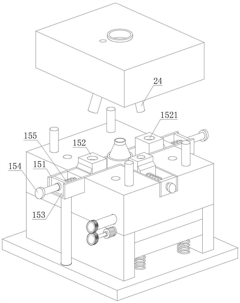
[0044] Step 2: The operator clamps the positioning groove 211 at the lower end of the pressure plate 21 with the positioning column 17 at the upper end of the mold base 13, the first core 24 penetrates the core-pulling hole 1521 and engages with the clamping groove 133, and the pressure plate 21 is tightly connected to the mold base 13 fit;

[0045] Step 3: Injection molding by injecting injection molding fluid into the injection port 22;

[0046] Step 4: Lift the pressing plate 21 after forming, and when the first core 24 moves upward, when passing the scraper 15222, the lubricating o...

Embodiment 2

[0049] see figure 1 , figure 2 and image 3 , a shirt collar mold machine with a multi-directional core-pulling mechanism, comprising a lower mold 1 and an upper mold 2, the upper mold 2 is movably installed on the upper end of the lower mold 1, and the lower mold 1 includes a base 11, a support 12, and a mold base 13 , Groove 14, upper core-pulling mechanism 15, lower core-pulling mechanism 16 and positioning column 17, the support 12 is arranged on the upper end of the base 11, the mold base 13 is fixedly installed on the upper end of the support 12, and the groove 14 is arranged on the mold base 13, there are three groups of upper core-pulling mechanisms 15, and the upper core-pulling mechanisms 15 of the three groups are all arranged on the upper surface adjacent to the mold base 13, and the lower core-pulling mechanism 16 runs through the mold base 13 and is arranged on the The lower end of the upper core-pulling mechanism 15; the upper mold 2 includes a pressing plate...


PUM


Abstract

The invention discloses a shirt collar type mold machine with a multi-directional core pulling mechanism. The shirt collar type mold machine comprises a lower mold and an upper mold, wherein a slidingsleeve is a component made of stainless steel materials and is arranged inside a groove, so that sliding of a sliding block is facilitated; the sliding block is arranged inside the sliding sleeve, afixing block is fixedly arranged inside the sliding sleeve, a pull rod penetrates through the fixing block and is fixedly connected with the sliding block, a spring is fixedly arranged on the outer surface of the pull rod, and the two ends of the spring are connected with the sliding block and the fixing block respectively; and a pressing plate is lifted after forming, a first mold core drives thesliding block to move towards the two sides along the sliding sleeve in the upward moving process, the spring is compressed, a clamping ring is fixedly arranged on the inner wall of a core pulling hole, and a scraper is fixedly connected with the inner wall of the clamping ring. According to the shirt collar type mold machine, the lower end of the first mold core is wrapped by lubricating oil ofa sponge layer, then the first mold core is brought into the core pulling hole, when the first mold core passes through the scraper, the lubricating oil and burrs are scraped off by the scraper, the deburring effect is good, the lubricating oil is left in the core pulling hole, and the effect of lubricating the first mold core can be achieved conveniently.

Description

technical field [0001] The invention relates to the technical field of mold machines, in particular to a shirt collar mold machine with a multi-directional core-pulling mechanism and an implementation method thereof. Background technique [0002] Mold machinery is a tool used to shape objects. This tool is composed of various parts. Different molds are composed of different parts. Mold machinery mainly realizes the processing of the shape of objects by changing the physical state of the formed material. It is used under the action of external force in blanking, forming stamping, die forging, cold heading, extrusion, pressing of powder metallurgy parts, die casting, and compression molding or injection molding of engineering plastics, rubber, ceramics and other products. Blanks become tools for workpieces of specific shape and size. [0003] However, the core-pulling mechanism of the mold machine is driven by an oil cylinder to complete the core-pulling. During the process o...

Claims


Application Information

Patent Timeline
Patent Type & Authority Applications(China)
IPC IPC(8): B29C45/26B29C45/33B29C45/83B29C37/02
CPCB29C37/02B29C45/2602B29C45/33B29C45/332B29C45/83B29C2045/334
Inventor 姜荣香
Owner 河北万发服装纺织集团有限公司
Why Eureka
Try Eureka