Cone warping machine and method for operating same

A slit warping machine, warping technology, applied in the direction of warping machines, textile and papermaking, other manufacturing equipment/tools, etc.

Active Publication Date: 2020-12-15
KARL MAYER STOLL R&D GMBH
View PDF4 Cites 1 Cited by
  • Summary
  • Abstract
  • Description
  • Claims
  • Application Information

AI Technical Summary

Problems solved by technology

However, the user still has to manually complete several processing steps

Method used


Image

  • Cone warping machine and method for operating same
  • Cone warping machine and method for operating same
  • Cone warping machine and method for operating same

Examples


Embodiment Construction

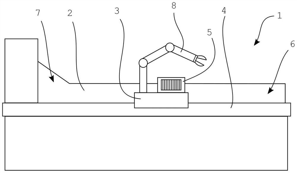
[0046] figure 1 A schematic diagram of a section warping machine 1 according to the invention is shown. The section warping machine 1 has a warping cylinder 2 and a warping table 3 . The warping cylinder 2 can be driven in rotation by an electric motor and, moreover, the warping cylinder can be moved parallel to its longitudinal axis. The warping table 3 is guided and displaceable on a side rail 4 , wherein the warping table 3 moves parallel to the longitudinal axis of the warping cylinder 2 . The warping reed 5 is placed on the warping table 3, through which the yarn, for example from the yarn creel, is supplied to the section warping machine and bundled. The bundled yarns together form a warp sliver.

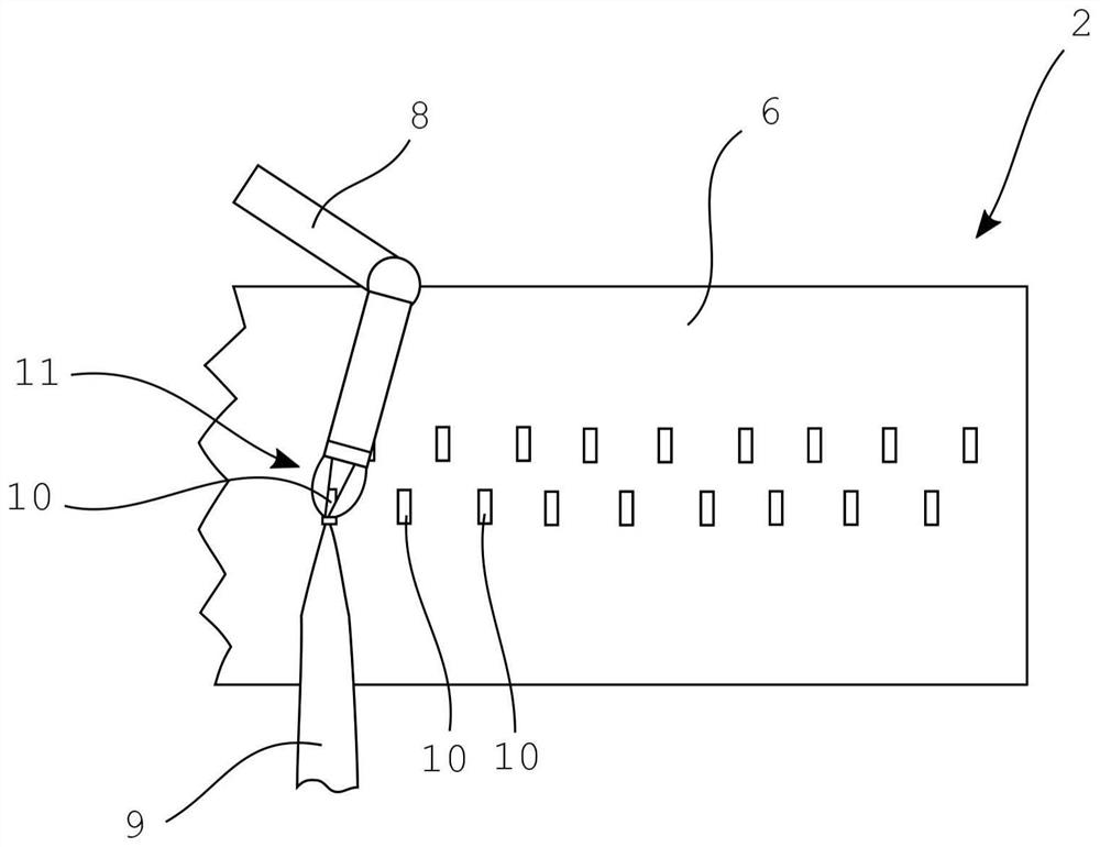
[0047] In order to start the warping process, first the warping cylinder 2 and the warping table 3 are moved relative to each other so that the warping table 3 is opposite the warping initial zone 6 of the warping cylinder 2 . The sliver of warp thread is now fixed on the ...


PUM


Abstract

The invention relates to a cone warping machine and a cone warping machine operation method. The cone warping machine (1) is provided with a warping roller (2) and a warping table (3) arranged besidethe warping roller (2), a warping reed (5) used for yarn input is arranged on the warping table, the warping roller (2) and the warping table (3) can move relative to each other, and the cone warpingmachine (1) is provided with a mechanical arm (8). According to the invention, the mechanical arm (8) of the cone warping machine (1) has at least one means for actuating the warp slivers (9). The invention also relates to a method for operating the cone warping machine (1), comprising the following steps: moving the warping roller (2) of the cone warping machine (1) and the warping table (3) of the cone warping machine (1) relative to each other until the warping table (3) faces a warping start zone (6) of the warping roller (2), receiving a warp sliver (9) from the warping table (3) by meansof the mechanical arm (8) of the cone warping machine (1), and the warp sliver (9) is fixed on the warping roller (2) through the mechanical arm (8) in the warping start zone (6).

Description

technical field [0001] The invention relates to a section warping machine, which has a warping cylinder and a warping table arranged beside the warping cylinder, and a warping reed for yarn input is installed on the warping table, wherein the warping cylinder and the warping table are movable relative to each other, and the section warper has a robotic arm. Background technique [0002] With the section warping machine, individual yarns from yarn creels are warped side by side. A group of yarns is supplied to the section warping machine via a warping reed, which is placed on the warping table of the section warping machine. The yarns are gathered into a warp sliver in which the yarns are arranged side by side. The warp slivers are wound onto warping cylinders during the warping process. During the warping process, the warping cylinders rotate. The warping table and the warping cylinder are moved parallel to the longitudinal axis of the warping cylinder and relative to ea...

Claims


Application Information

Patent Timeline
Patent Type & Authority Applications(China)
IPC IPC(8): D02H3/00D02H13/00
CPCD02H3/04D02H13/00D02H3/02D02H13/36
Inventor R·科恩M·富尔
Owner KARL MAYER STOLL R&D GMBH
Why Eureka
Try Eureka