Floor device capable of preventing electric shock in transformer substation

A technology for substations and floors, applied in the field of substations, can solve the problems of heat accumulation, hidden safety hazards, and the natural cooling effect is not very good, and achieve the effect of alleviating high temperature and being easy to step on.

Inactive Publication Date: 2020-12-15
曲周县旭如鑫贸易有限公司
View PDF0 Cites 2 Cited by
  • Summary
  • Abstract
  • Description
  • Claims
  • Application Information

AI Technical Summary

Problems solved by technology

[0002] Existing substations are generally located in sparsely populated areas. If a problem occurs, it cannot be repaired in time, and the equipment inside the substation will generate a lot of heat during operation. Although there is an exhaust port, the effect of natural cooling is not very good, and the existing A complete substation will lay a complete insulating floor on the ground, but this will cause heat to accumulate inside the substation, which will have a great impact on the life of the equipment and insulation materials, and if the ground inside the substation is closed, if it encounters stagnant water, it cannot be repaired in time. Discharge will cause great safety hazards. The floor of the existing substation does not have the functions of automatic lifting insulation board and heat dissipation and drainage. A floor device for preventing electric shock in the substation described in the present invention can solve the above problems

Method used


Image

  • Floor device capable of preventing electric shock in transformer substation
  • Floor device capable of preventing electric shock in transformer substation
  • Floor device capable of preventing electric shock in transformer substation

Examples


Embodiment Construction

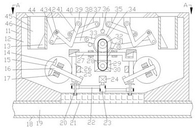
[0017] Combine below Figure 1-4 The present invention is described in detail, wherein, for the convenience of description, the orientations mentioned below are now defined as follows: figure 1 The projection relationship of itself is the same as the up, down, left, right, front, and rear directions.

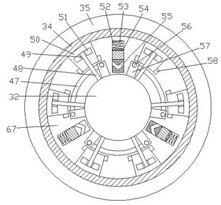
[0018] The floor device for preventing electric shock in a substation according to the present invention includes a box body 11, a cavity 12 is arranged in the box body 11, and a main pulley 32 is rotatably connected to the inner wall of the front side of the cavity 12. The outer side of the main pulley 32 is provided with a rotating ring 34 that is symmetrical about the center of the main pulley 32, and a connecting cavity 67 is provided between the rotating ring 34 and the main pulley 32. The rear side of the main pulley 32 is rotatably connected to a The inner wall of the rear side of the cavity 12 is rotatably connected to the fixed plate 35 of the rotating ring 34 . A sli...


PUM


Abstract

The invention discloses a floor device capable of preventing electric shock in a transformer substation. The device comprises a box body, wherein a cavity is formed in the box body, a main belt wheelis rotatably connected to the inner wall of the front side of the cavity, a rotating ring which is symmetric about the center of the main belt wheel is arranged on the outer side of the main belt wheel, and a connecting cavity is formed between the rotating ring and the main belt wheel. The device is arranged on the ground of the transformer substation and used for preventing high-voltage electricity from touching the ground to injure maintenance personnel, has the functions of heat dissipation and water drainage, can effectively relieve high temperature in the transformer substation and accidents of water logging, and can lift an insulating plate when the high-voltage electricity touches the ground, and the insulating plate is still in a horizontal state after lifting, so that the maintenance personnel can tread the insulating plate conveniently, the insulating plate can move only when a motor is started, and safety is achieved.

Description

technical field [0001] The invention relates to the field of substations, in particular to a floor device for preventing electric shock in a substation. Background technique [0002] Existing substations are generally located in sparsely populated places. If there is a problem, it cannot be repaired in time, and the equipment inside the substation will generate a lot of heat during operation. Although there are exhaust ports, the effect of natural cooling is not very good. The substation will lay a complete insulating floor on the ground, but this will cause heat to accumulate inside the substation, which will have a great impact on the life of the equipment and the insulation material, and if the ground inside the substation is closed, it will not be able to meet water in time. Exhaust will cause great safety hazards. The existing substation floor does not have the functions of automatic lifting insulation board, heat dissipation and drainage. The electric shock prevention ...

Claims


Application Information

Patent Timeline
Patent Type & Authority Applications(China)
IPC IPC(8): E04F15/02E04H5/04H02B7/00E03F3/04
CPCE03F3/04E04F15/02E04H5/04H02B7/00
Inventor 武三家
Owner 曲周县旭如鑫贸易有限公司
Why Eureka
Try Eureka