

Hydraulic engineering impeller based on high-speed centrifugal magnetic pole cutters
A water conservancy project and high-speed centrifugation technology, which is applied to components of pumping devices for elastic fluids, hydropower, non-variable pumps, etc., can solve problems such as clogged impellers and particle residues at the drainage end that cannot be cleaned. To achieve effective utilization, reduce the number of repairs and maintenance, and improve the service life
- Summary
- Abstract
- Description
- Claims
- Application Information
AI Technical Summary
Problems solved by technology
Method used
Image


Examples
Embodiment example 1
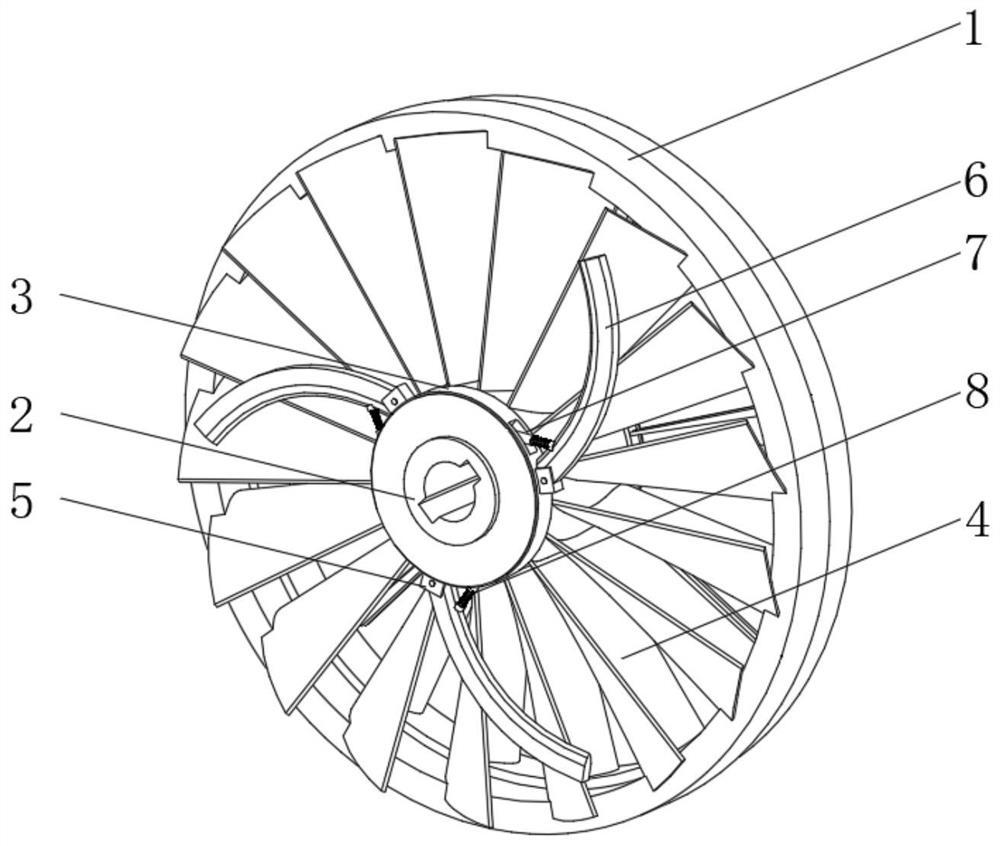
[0041] see Figure 1-4, the present invention provides a technical solution: a water conservancy project impeller based on a high-speed centrifugal pole cutter, including a wheel body 1, a central shaft body 2, an outer ring shaft 3 and an impeller body 4, and the outer ring shaft 3 is installed on the central shaft body 2. On the outer side, the central shaft body 2 and the outer ring sleeve shaft 3 are rotationally connected to the wheel body 1 through a connecting frame;
[0042] The outside of the outer ring sleeve shaft 3 is fixedly connected with a rotating seat 5, and the outer side of the rotating seat 5 is rotatably connected with a retractable inner cutting crushing knife 6, and the outer ring sleeve shaft 3 is located on the inside of the retractable inner cutting crushing knife 6. An inner groove 7 is provided. The inner tank 7 is placed with a recovery reset device 8, and the recovery reset device 8 is connected to the side of the inner tank 7 away from the retrac...
Embodiment example 2
[0046] see Figure 1-5 , on the basis of the first embodiment, the present invention provides a technical solution: the recovery and reset device 8 includes a main body cavity 81, an inner connecting rod 82 and a top connecting seat 83, the inner connecting rod 82 is slidably connected with the main body inner cavity 81, and the inner The top of the connecting rod 82 is fixedly connected with the top connecting seat 83, the outer side of the inner connecting rod 82 is located between the inner connecting rod 82 and the top connecting seat 83, and the outer tension spring 84 is sleeved, and the inner side of the main body cavity 81 is provided with a waterproof ring 88, The waterproof ring 88 is slidably connected with the inner connecting rod 82, and the recovery reset device adopts a double spring design, which can ensure the buffer return performance of the device when the device is subjected to centrifugal force.
[0047] The inner bottom of the inner cavity 81 of the main ...
Embodiment example 3
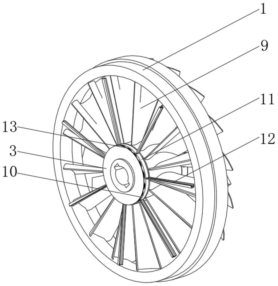
[0050] see Figure 1-7 , on the basis of the implementation case 1 and the implementation case 2, the present invention provides a technical solution: the cleaning mechanism 12 in the impeller includes a cleaning part body 121, and both sides of the cleaning part body 121 are provided with fixed side cleaning racks 122, fixed Type side cleaning frame 122 inner side is provided with reinforcement steel wire positioning shape layer, and cleaning part body 121 is provided with inner cleaning protrusion 123, and cleaning part body 121 is positioned between inner cleaning protrusion 123 and is provided with movable reset cleaning assembly, inside the impeller The cleaning mechanism 12 adopts reinforced side components to ensure the stability of the entire component. There are multiple inwardly folded cleaning parts on the inside of the device, and multiple internal cleaning protrusions are set inside it, which can effectively remove the cleaning parts during cleaning. Impurities in...
PUM
 Abstract
Description
Claims
Application Information