Pump impeller, lye pump, household appliance and method for producing pump impeller

A technology for household appliances and pump impellers, applied in the field of pump impellers, can solve the problems that the necessary operation of the pump cannot be fully ensured, it is no longer possible to achieve, and the pump power is unfavorable, so as to achieve a simple drive speed adjustment device, avoid current peaks, and avoid power effect of loss

Pending Publication Date: 2020-12-15
BSH BOSCH & SIEMENS HAUSGERAETE GMBH
View PDF6 Cites 0 Cited by
  • Summary
  • Abstract
  • Description
  • Claims
  • Application Information

AI Technical Summary

Problems solved by technology

Objects being transported together may hit the surface of the pump impeller during the pumping process and in particular may damage said surface due to their kinetic energy, so that the geometry of the pump impeller changes to such an extent that this geometry change is about Aspects of delivery flow and pressure build-up may have adverse effects on pump performance
As a result, the necessary operation of the pump, in which the pump impeller is installed, may not be sufficiently ensured during the service life of the pump
In other words, the pump impeller can be damaged in such a way that it is no longer possible to reach the originally intended operating point of the pump (pressure-delivery flow relationship)

Method used


Image

  • Pump impeller, lye pump, household appliance and method for producing pump impeller
  • Pump impeller, lye pump, household appliance and method for producing pump impeller
  • Pump impeller, lye pump, household appliance and method for producing pump impeller

Examples


Embodiment Construction

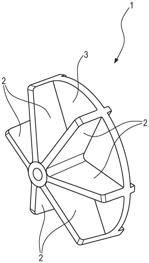
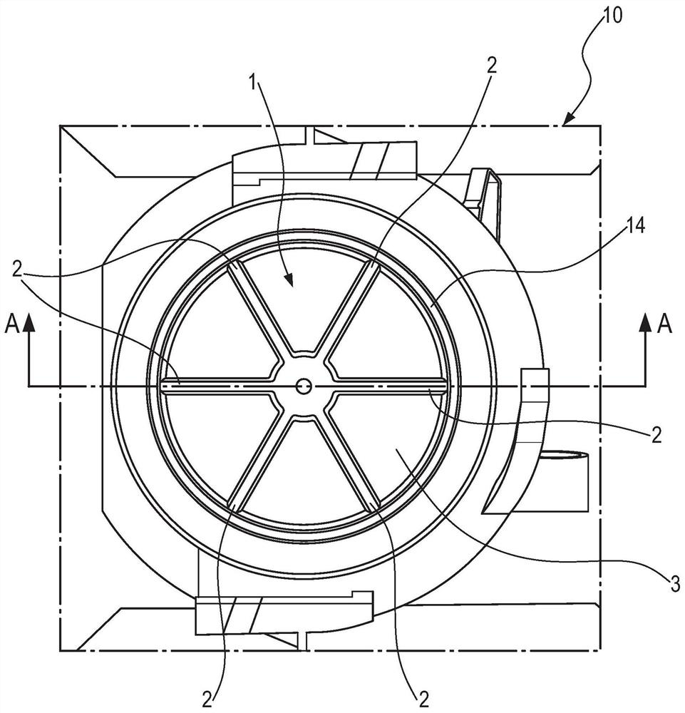
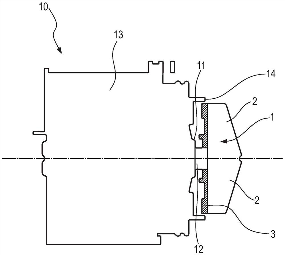
[0041] figure 1 A pump impeller 1 according to an embodiment of the invention is shown. The pump impeller 1 includes a working wheel blade 2 and a working wheel disk 3 . In this case, the rotor blades 2 are arranged on one side of the rotor disk 3 . The impeller blades 2 extend in the radial direction of the impeller disk 3 and at right angles thereto. The present embodiment comprises six impeller blades 2 .

[0042] The pump impeller 1 consists of a base material, that is to say both the impeller blades 2 and the impeller disk 3 consist of a base material. Furthermore, the radially outermost parts of the rotor blades 2 and of the rotor disk 3 (ie the region of the outer edge of the rotor disk 3 between 2 mm and 5 mm) are coated with an outer layer material. The outer material is softer than the base material. According to a further embodiment, the working wheel 3 comprises a circumferential flange which is arranged on the circumferential surface of the working wheel 3 an...


PUM


Abstract

The invention relates to a pump impeller (1) for a household appliance, comprising impeller blades (2), the pump impeller (1) being made of a base material, and the base material being at least partially coated with a permanently elastic outer layer material that is softer than the base material.

Description

technical field [0001] The invention relates to a pump impeller, a lye pump with a pump impeller, a household appliance with the lye pump and a method for producing the pump impeller. Background technique [0002] The pump impellers of pumps, which are used, for example, in lye pumps for domestic appliances, are often subjected to high loads due to the objects transported together with the fluid to be pumped. This fluid can in particular be an alkaline solution (ie a single-phase fluid) or a mixture of foam and water (ie a two-phase fluid). Depending on the type of household appliance, the objects may be, for example, coins, office clips, hard food remnants and the like. The household appliance may be, for example, a washing machine, a washer-dryer, a laundry dryer, a dish rinser, or the like. Objects being transported together may hit the surface of the pump impeller during the pumping process and in particular may damage said surface due to their kinetic energy, so that ...

Claims


Application Information

Patent Timeline
Patent Type & Authority Applications(China)
IPC IPC(8): F04D29/22F04D7/06F04D29/043F04D13/02B29B11/04B29C45/14D06F39/08A47L15/42
CPCF04D29/2227F04D29/2266F04D29/2222F04D7/06F04D29/043F04D13/02B29B11/04B29C45/14D06F39/085A47L15/4225B29L2031/082B29C45/1676F04D29/086B29L2031/7496
Inventor K·哈恩R·勒默尔J·斯格里派克
Owner BSH BOSCH & SIEMENS HAUSGERAETE GMBH
Why Eureka
Try Eureka