
Patsnap Eureka
For R&D, Patsnap Eureka makes reading and utilizing patents & technical documents easy.
Patsnap Eureka AIR
Designed for self-driven R&D workflows. Generate viable solutions, solve complex R&D challenges, empower your innovation with AI.

Patsnap Eureka Materials
Designed for material experts only. Revolutionize your material R&D, from search, analyze, to developing new materials.

TechResearch
Generate reliable direction feasibility study reports for your R&D in just a few steps.

TechSeek
Discover and master advanced knowledge NOW. Basics, ideas, possibilities, all at once.

TechMind
As an expert in R&D Theories, TechMind can generates customized viable solutions instantly.

TechRisk
Analyze your overall solution with one click, know your potential R&D risks in advance.

TechMonitor
Get weekly tech updates, stay abreast of the latest tech innovations and key insights.
Vacuum degree real-time monitoring device for vacuumizing operation
A real-time monitoring, vacuum degree technology, applied in measuring devices, vacuum gauges, measuring fluid pressure, etc., can solve the problem of inability to accurately monitor the gas chamber in real time, and achieve the goal of reducing vacuuming time, saving time wastage, and eliminating measurement errors. Effect
- Summary
- Abstract
- Description
- Claims
- Application Information
AI Technical Summary
Problems solved by technology
Method used
Image

Examples
Embodiment 1
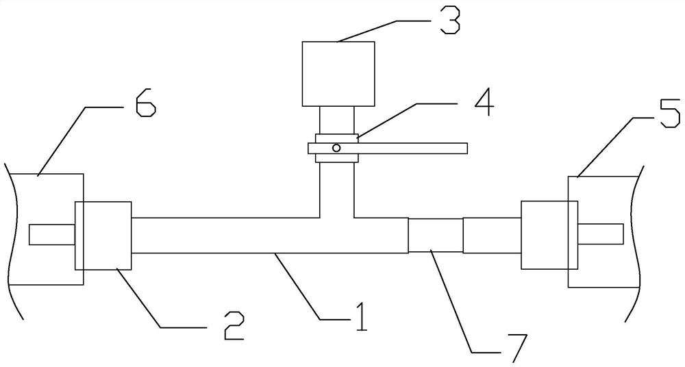
[0024] A real-time monitoring device for vacuum degree of vacuuming operation in this embodiment, such as figure 1 As shown, it includes adapter 1, standard air chamber special joint 2, electronic vacuum gauge 3 and stop valve 4.
[0025] The adapter 1 is a three-way adapter, the standard air chamber special joint 2 is respectively arranged on the first end and the second end of the adapter 1, and the third end of the adapter 1 is connected to the electronic vacuum gauge 3 through the shut-off valve 4 . The special connector 2 for the standard air chamber is used to connect the gas outlet of the GIS air chamber 5 and the vacuum pipeline of the vacuum pump unit 6 . Use the special connector 2 for the standard air chamber to connect the vacuum pipes of the GIS air chamber 5 and the vacuum pump unit 6, so that the device has no installation direction, strong adaptability and versatility, and is easy to install.
[0026] In this embodiment, the special joint 2 for the standard ai...
Embodiment 2
[0029] A real-time monitoring device for vacuum degree of vacuuming operation in this embodiment, such as figure 1 As shown, it includes adapter 1, standard air chamber special joint 2, electronic vacuum gauge 3 and stop valve 4. A vacuum degree compensation module 7 is arranged in the adapter 1 , and the vacuum degree compensation module 7 is arranged at an end of the adapter 1 close to the GIS air chamber 5 .
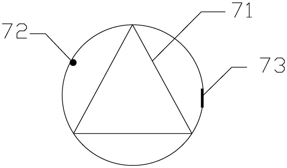
[0030] The vacuum compensation module 7 includes a compensation channel 71, a transmitter and a receiver. The transmitter and the receiver are respectively arranged on both sides of the compensation channel 71. The compensation channel 71 is arranged in the channel of the adapter 1. The transmitter emits gas as a transmission medium signal.
[0031] Such as figure 2 As shown, the emitter in this embodiment is a polychromatic light source 72, the receiver is a color sensor 73, and the compensation channel 71 is a hollow triangular prism or a hollow trapezoidal brick...
Embodiment 3
[0037] A real-time monitoring device for vacuum degree of vacuuming operation in this embodiment, such as figure 1 As shown, it includes adapter 1, standard air chamber special joint 2, electronic vacuum gauge 3 and stop valve 4. A vacuum degree compensation module 7 is arranged in the adapter 1 , and the vacuum degree compensation module 7 is arranged at an end of the adapter 1 close to the GIS air chamber 5 .
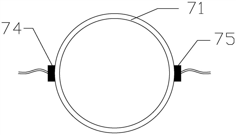
[0038] The vacuum compensation module 7 includes a compensation channel 71, a transmitter and a receiver. Such as image 3 As shown, the transmitter in this embodiment is an acoustic wave generator 74 , and the receiver is an acoustic wave receiver 75 . The sound wave generator 74 and the sound wave receiver 75 are respectively arranged on both sides of the compensation channel 71 . The sound wave generator 74 generates sound waves of a certain frequency, and the sound wave receiver 75 receives the sound waves at the other side of the compensation channel 71 .
[...
PUM
 Abstract
Description
Claims
Application Information
 - R&D Engineer
- R&D Manager
- IP Professional
- Industry Leading Data Capabilities
- Powerful AI technology
- Patent DNA Extraction
Browse by: Latest US Patents, China's latest patents, Technical Efficacy Thesaurus, Application Domain, Technology Topic, Popular Technical Reports.
© 2024 PatSnap. All rights reserved.Legal|Privacy policy|Modern Slavery Act Transparency Statement|Sitemap|About US| Contact US: help@patsnap.com