
Invisible tooth socket with traction accessory and manufacturing method of invisible tooth socket

A technology of invisible braces and a manufacturing method, applied in the field of dental instruments, can solve problems such as easy deformation, warping and scratching of oral mucosa, and achieve the effects of not easily deformed and improved comfort.

Pending Publication Date: 2020-12-18
深圳爱舒笑科技有限公司
View PDF0 Cites 4 Cited by
  • Summary
  • Abstract
  • Description
  • Claims
  • Application Information

AI Technical Summary

Problems solved by technology

On the one hand, the position and angle of the cutting opening are often limited. On the other hand, the opening is easily deformed, tilted and scratched the oral mucosa. Therefore, it is urgent to develop a new type of invisible braces with traction accessories, which can realize 360 ​​degrees without dead angle. traction without irritating the oral mucosa

Method used


Image

  • Invisible tooth socket with traction accessory and manufacturing method of invisible tooth socket
  • Invisible tooth socket with traction accessory and manufacturing method of invisible tooth socket
  • Invisible tooth socket with traction accessory and manufacturing method of invisible tooth socket

Examples


Embodiment 1

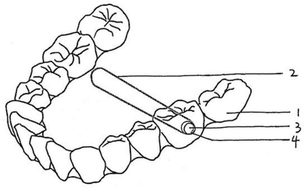
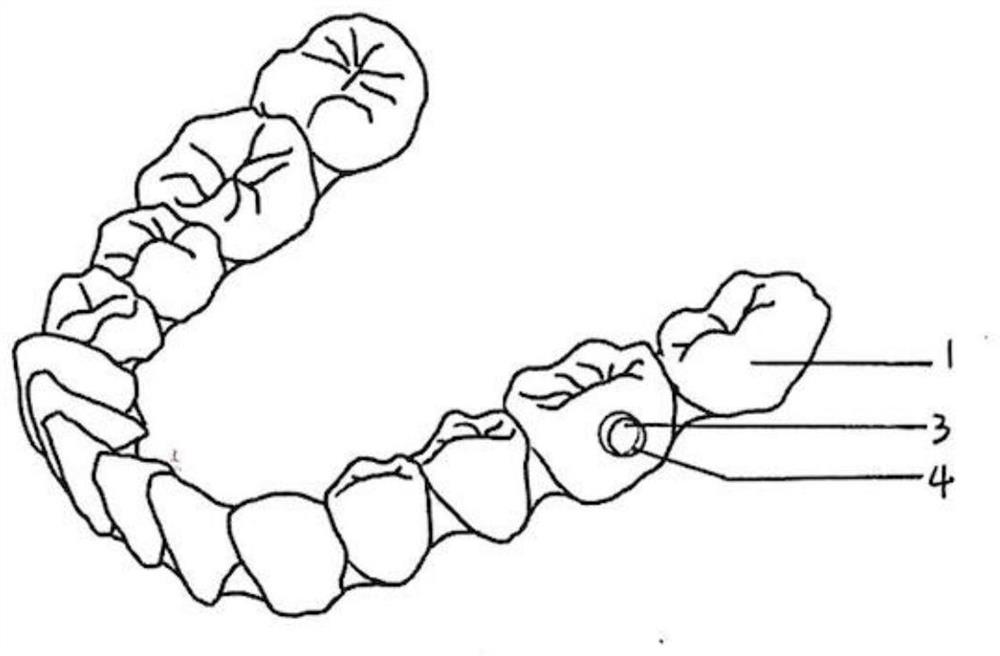
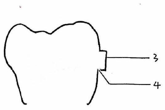
[0030] An invisible brace with traction accessories and a manufacturing method thereof, comprising an invisible brace body (1) and a dynamic rope (2), the brace body (1) is provided with local protrusions (31), (32), The bottom of the protrusion is provided with notches (41), (42) which are cut smoothly, and the accompanying drawing uses two small short lines to mark the start and end points of the notches, and the power rope (2) can be fixed through the notches (41), (42) .

[0031] A local protrusion (31) is provided at the center of the buccal surface of the maxillary canine, and a local protrusion (32) is provided at the center of the buccal surface of the mandibular first molar on the same side.

[0032] Preferably, the partial protrusion may be cylindrical, with a diameter of 4 mm and a height of 2 mm.

[0033] The notch (41) of the maxillary canine is near the mesial side near the gingiva. The gap (42) of the mandibular molars is near the gingiva side and is near the ...

Embodiment 2

[0039] Compared with Example 1, as another embodiment, a local protrusion (31) is provided at the center of the buccal surface of the mandibular canine, and a local protrusion (32) is provided at the center of the buccal surface of the maxillary first molar on the same side. The notch (41) of the mandibular canine is close to the mesial side near the gingiva. The gap (42) of the maxillary molars is near the gingiva and near the distance. The specific implementation is similar to the above example, realizing the common type III traction in orthodontics, providing sufficient anchorage for the mandibular molars backward, and avoiding the stimulation of the oral mucosa by cutting the opening at the edge of the brace.

Embodiment 3

[0041] Compared with Example 1, as another implementation mode, local protrusions (31), (32) are set in the center of the buccal surface of the teeth on both sides of the impacted teeth, and the gaps (41), (42) are all close to the occlusal side. Ambush teeth are affixed with brackets after the operation is exposed, and two dynamic rope one ends are hung on gap (41), (42) respectively, and the other ends are all hung on the brackets of the embedded teeth. The other specific implementations are similar to the above-mentioned examples, which realize the traction of the impacted teeth and avoid the stimulation of the oral mucosa by cutting the openings at the edge of the braces.


PUM

PropertyMeasurementUnit
diameteraaaaaaaaaa
heightaaaaaaaaaa
diameteraaaaaaaaaa

Abstract

The present invention discloses an invisible tooth socket with a traction accessory. The invisible tooth socket with the traction accessory comprises an invisible tooth socket body and further comprises a power rope, the tooth socket body is provided with a local protrusion, a bottom part of the protrusion is provided with a notch which is cut smoothly, one end of the power rope is fixed through the notch, and the other end of the power rope can be fixed to the other traction accessory or hung on an implantation nail, a tongue side buckle and a bracket. The present invention further disclosesa manufacturing method of the invisible tooth socket with the intermaxillary traction accessory. The manufacturing method sequentially comprises the following steps: (1) obtaining an accurate tooth jaw digital model through a predetermined method; (2) placing an accessory with a preset shape at a specific tooth surface by utilizing a software; (3) manufacturing a tooth socket body based on the tooth jaw model in the step (2); and 4) cutting a notch at a specific position of a bottom part of a protrusion on the tooth socket body in the step 3) by using a cutting tool. Through a combination of the tooth socket body and the power rope, 360-degree dead-angle-free traction can be realized, so that more possibilities are provided for invisible orthodontics, such as pushing molar teeth backwards,pulling buried teeth and the like.

Description

technical field [0001] This application relates to the field of dental instruments, especially to an invisible brace with a traction attachment and its manufacturing method Background technique [0002] During orthodontic treatment, any force applied to the orthodontic tooth to move it must simultaneously produce a force in the opposite direction and the same magnitude, and the structure that can resist the reaction of the orthodontic force is called anchorage. Teeth are often used as anchorage in orthodontic treatment. The anchorage teeth will resist the reaction force generated by the orthodontic force. Usually, the anchorage teeth are not expected to move, so the anchorage must be effectively controlled. Commonly used methods include using the upper jaw (upper dental arch) or the lower jaw (lower dental arch) as anchorages to correct the opposing teeth or the interaction between the upper and lower jaws to adjust the jaw relationship, such as Class II and Class III tracti...

Claims


Application Information

Patent Timeline
Patent Type & Authority Applications(China)
IPC IPC(8): A61C7/08A61C7/10A61C7/28B29C64/10B33Y10/00
CPCA61C7/08A61C7/10A61C7/28B29C64/10B33Y10/00
Inventor 付益慧付益驰
Owner 深圳爱舒笑科技有限公司
Learn More