
Disinfection structure and medical instrument disinfection cabinet with same

A technology for disinfection cabinets and gears, which is applied in the direction of disinfection, sanitary equipment for toilets, water supply devices, etc. It can solve the problems of no flip structure, long use time, and reduced disinfection efficiency, so as to improve disinfection efficiency, spray comprehensively, and improve disinfection. effect of effect

Inactive Publication Date: 2020-12-18
苑志明
View PDF0 Cites 2 Cited by
  • Summary
  • Abstract
  • Description
  • Claims
  • Application Information

AI Technical Summary

Problems solved by technology

[0002] Medical equipment disinfection cabinet refers to the sterilization, disinfection, heat preservation and dehumidification of medical equipment, special surgical equipment, towels, clothing, tableware, medical facilities and other items through ultraviolet rays, far infrared rays, high temperature (high temperature disinfection through heating tubes), ozone, etc. When the disinfection cabinet sterilizes medical equipment, it needs a disinfection structure, but the existing medical equipment disinfection cabinet generally does not have a flip structure, which makes some parts unable to be sterilized during the disinfection process, resulting in disinfection effect Poor, or extremely long time, leading to a reduction in disinfection efficiency, and when placing medical instruments, they are generally laid in the disinfection cabinet, which will also lead to incomplete disinfection, which may affect the disinfection effect, and during the disinfection process, it may be It leads to confusion in the placement of instruments, which is not conducive to the arrangement of sterilized instruments

Method used


Image

  • Disinfection structure and medical instrument disinfection cabinet with same
  • Disinfection structure and medical instrument disinfection cabinet with same
  • Disinfection structure and medical instrument disinfection cabinet with same

Examples


Embodiment Construction

[0021] The technical solutions of the present invention will be clearly and completely described below in conjunction with the embodiments. Apparently, the described embodiments are only some of the embodiments of the present invention, not all of them. Based on the embodiments of the present invention, all other embodiments obtained by persons of ordinary skill in the art without creative efforts fall within the protection scope of the present invention.

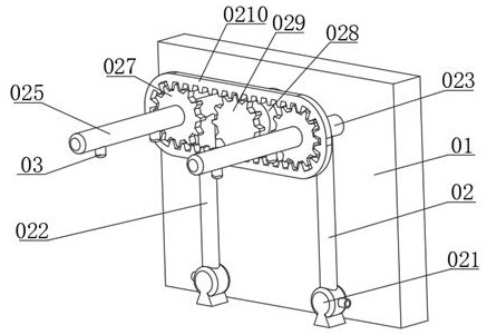
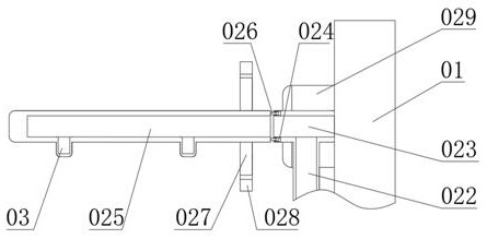
[0022] Such as Figure 1-2 As shown, a disinfection structure includes a mounting plate 01 and a disinfection assembly 02, and a disinfection assembly 02 is fixed on one side of the installation plate 01; Pipe 025, sealing pipe 026, first gear 027, toothed belt 028, first motor 029 and second gear 0210, a water pump 021 is installed symmetrically on the bottom of one side of the mounting plate 01, and a pumping pump is connected to the top of the water pump 021. The water pipe 022, the fixed pipe 023 is symmetrically fixed...


PUM


Abstract

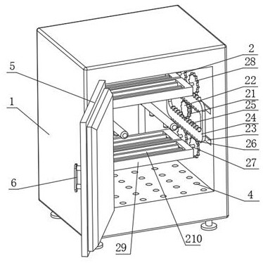
The invention discloses a disinfection structure and a medical instrument disinfection cabinet with the same. A disinfection assembly is fixed outside one side of a mounting plate; the disinfection assembly comprises water pumps, water pumping pipes, fixed pipes, rotating grooves, rotating pipes, sealing pipes, a first gear, a toothed belt, a first motor and a second gear; the water pumps are symmetrically installed outside the bottom end of one side of the mounting plate; the interiors of the top ends of the water pumps are connected with the water pumping pipes in a penetrating mode; the fixed pipes are symmetrically and fixedly installed on the plate surface of one side of the mounting plate; the other ends of the water pumping pipes are connected into the fixed pipes in a penetrating mode; and the rotating pipes are symmetrically installed outside one sides of the fixed pipes. According to the medical instrument disinfection cabinet, the disinfection device is adopted, high-degreealcohol is used for spraying medical instruments for first-step disinfection, and spraying is more comprehensive through a rotating structure, so that the disinfection effect and the disinfection efficiency are improved; a clamping and overturning device is further adopted, so that the instruments can be clamped and overturned, disinfection is more comprehensive, the disinfection efficiency is improved, and arrangement of the disinfected instruments is facilitated.

Description

technical field [0001] The invention relates to the field of medical disinfection equipment, in particular to a disinfection structure and a disinfection cabinet for medical instruments. Background technique [0002] Medical equipment disinfection cabinet refers to the sterilization, disinfection, heat preservation and dehumidification of medical equipment, special surgical equipment, towels, clothing, tableware, medical facilities and other items through ultraviolet rays, far infrared rays, high temperature (high temperature disinfection through heating tubes), ozone, etc. When the disinfection cabinet sterilizes medical equipment, it needs a disinfection structure, but the existing medical equipment disinfection cabinet generally does not have a flip structure, which makes some parts unable to be sterilized during the disinfection process, resulting in disinfection effect Poor, or extremely long time, resulting in lower disinfection efficiency, and when placing medical ins...

Claims


Application Information

Patent Timeline
Patent Type & Authority Applications(China)
IPC IPC(8): A61L2/18A61L2/26
CPCA61L2/18A61L2/26
Inventor 苑志明
Owner 苑志明
Learn More