
Process method for repairing hydraulic dummy shaft

A process method and technology for false shafts, which are applied in metal processing, manufacturing tools, metal processing equipment, etc., can solve the problems of increased frequency of use of hydraulic false shafts, wear failure of threaded holes, and inability to expand threaded holes, reducing work volume, improve efficiency, and shorten the re-production cycle.

Active Publication Date: 2020-12-18
HARBIN ELECTRIC POWER EQUIP
View PDF7 Cites 0 Cited by
  • Summary
  • Abstract
  • Description
  • Claims
  • Application Information

AI Technical Summary

Problems solved by technology

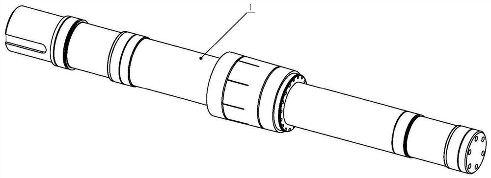
[0002] With the wide application of synchronous hoist motors, the frequency of use of the hydraulic dummy shaft of the hoist rotor has increased. Long-term use has caused the threaded hole at the end of the hydraulic dummy shaft to wear and fail to fit the hydraulic cover, which cannot meet the requirements of motor manufacturing and testing. The existing technology The repair method for a single thread adopts the method of adding a plug to reprocess the thread after reaming. Due to the special structure of this type of hydraulic dummy shaft, the distance between the threaded hole and the outer diameter edge of the shaft is small and the hole cannot be reamed. If the threaded hole fails, it can only be repaired. This shaft is scrapped and a new hydraulic dummy shaft is made. The material and production cost of the dummy shaft is huge and the cycle is long, such as figure 1 As shown in Fig. 1, the threaded hole in the taper part of the false axis is the threaded hole that is invalid and needs to be repaired

Method used


Image

  • Process method for repairing hydraulic dummy shaft
  • Process method for repairing hydraulic dummy shaft
  • Process method for repairing hydraulic dummy shaft

Examples


Embodiment Construction

[0037] A technical method for repairing a hydraulic false shaft:

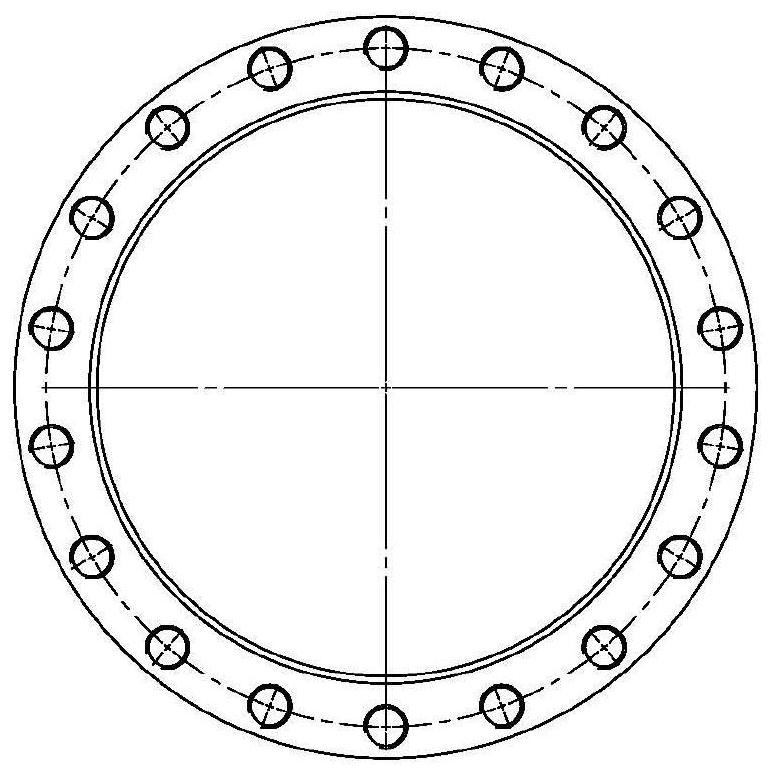
[0038] One, such as figure 1 Shown: cut off the shaft diameter of the failed thread in the hydraulic dummy shaft 1, chamfer the end of the processed hydraulic dummy shaft 1 by 1×3 to facilitate the introduction of the shaft sleeve 2 later, make the shaft sleeve 2, and heat the shaft sleeve 2 Installed on the shaft diameter of the hydraulic dummy shaft 1 and welded with the shaft of the hydraulic dummy shaft 1, inspect the welded part after welding, process according to the drawing of the hydraulic dummy shaft 1 after the inspection is qualified, and thread the threaded hole of the shaft sleeve 2 after processing After treatment, it can be used normally;

[0039] 2. Manufacturing steps of shaft sleeve 2:

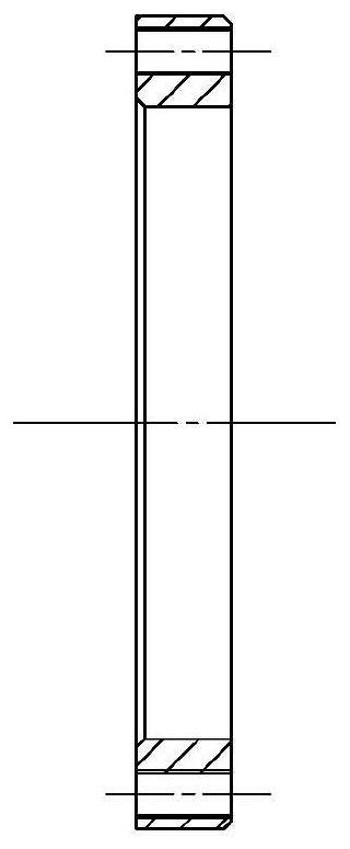
[0040] Such as figure 2 Shown:

[0041] ① According to the part of the outer diameter cut off by the hydraulic dummy shaft 1, a machining allowance of 22mm is left for the inner diameter and outer diamete...


PUM


Abstract

The invention relates to a process method for repairing a hydraulic dummy shaft. The process method comprises the following steps of: a shaft diameter of a thread failure part in the hydraulic dummy shaft (1) is cut off, chamfering 1*3 is performed at the end part of the processed hydraulic dummy shaft (1) to facilitate subsequent introduction of a shaft sleeve (2), the shaft sleeve (2) is manufactured, the shaft sleeve (2) is thermally installed on the shaft diameter of the hydraulic dummy shaft (1)and is welded with a shaft of the hydraulic dummy shaft (1), flaw detection is performed on thewelded part after welding, after flaw detection is passed, machining is conducted according to a drawing of the hydraulic dummy shaft (1), a threaded hole in the shaft sleeve (2) are subjected to wiredrawing treatment after machining, and the shaft sleeve can be normally used after treatment. The service life of the dummy shaft is prolonged, the dummy shaft is prevented from being scrapped due toabrasion failure of the threaded hole, the cost for manufacturing a dummy shaft is saved, the working efficiency is improved, and the operation is simple and convenient.

Description

Technical field: [0001] The invention relates to a technical method for repairing a hydraulic false shaft. Background technique: [0002] With the wide application of synchronous hoist motors, the frequency of use of the hydraulic dummy shaft of the hoist rotor has increased. Long-term use has caused the threaded hole at the end of the hydraulic dummy shaft to wear and fail to fit the hydraulic cover, which cannot meet the requirements of motor manufacturing and testing. The existing technology The repair method for a single thread adopts the method of adding a plug to reprocess the thread after reaming. Due to the special structure of this type of hydraulic dummy shaft, the distance between the threaded hole and the outer diameter edge of the shaft is small and the hole cannot be reamed. If the threaded hole fails, it can only be repaired. This shaft is scrapped and a new hydraulic dummy shaft is made. The material and production cost of the dummy shaft is huge and the cycl...

Claims


Application Information

Patent Timeline
Patent Type & Authority Applications(China)
IPC IPC(8): B23P9/00B23P11/02B23K31/02
CPCB23K31/02B23P9/00B23P11/02
Inventor 吴嘉兴黄秀波赵环宇王志威裴俊丰陈强郭晓明高明缙张晨光孙滨琦
Owner HARBIN ELECTRIC POWER EQUIP
Learn More