Machine tool disc chuck type centering device of tool clamp and centering method of machine tool disc chuck type centering device

A tooling fixture and centering device technology, which is used in positioning devices, manufacturing tools, metal processing machinery parts, etc., can solve the problems of aligning the fixture with knock, scratches on the machine tool table, and the decline in the accuracy of the spindle of the table. Reduced error, low cost, simple installation effect

Active Publication Date: 2020-12-18
AECC AERO SCI & TECH CO LTD
View PDF19 Cites 0 Cited by
  • Summary
  • Abstract
  • Description
  • Claims
  • Application Information

AI Technical Summary

Problems solved by technology

However, in the process of centering, some problems were encountered. For example, the faceplate of the machine tool is a flat workbench, and the bottom plate of the fixture is also a plane. The coincidence position sometimes differs by dozens of millimeters. Fortunately, it can be placed within a few millimeters. If it is a major fixture placed, these errors will cause a lot of friction after the fixture contacts the workbench plane. It is time-consuming and labor-intensive to move the fixture. The master worker uses iron rods to knock it out, and levers to pry it. After a long time, the machine tool workbench is severely scratched, and the fixture alignment belt will also be knocked. Injury, the spindle of the worktable will also be affected by the impact force of the alignment, resulting in a decrease in accuracy

Method used


Image

  • Machine tool disc chuck type centering device of tool clamp and centering method of machine tool disc chuck type centering device
  • Machine tool disc chuck type centering device of tool clamp and centering method of machine tool disc chuck type centering device
  • Machine tool disc chuck type centering device of tool clamp and centering method of machine tool disc chuck type centering device

Examples


Embodiment 1

[0038] refer to Figure 1-5 , the present invention provides a technical solution:

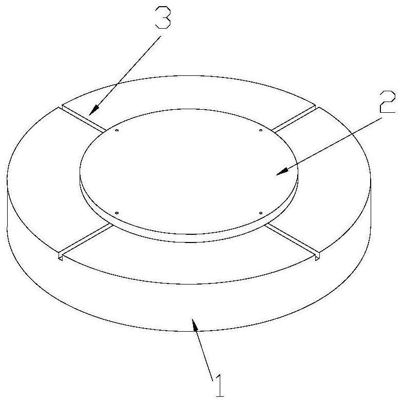
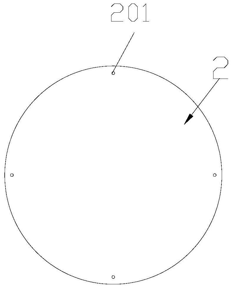
[0039] Please refer to Figure 1-4 , a type of centering device for a machine tool faceplate 1 of a fixture 2, comprising:

[0040] Machine face plate 1;

[0041] The tooling fixture 2 carried on the faceplate 1 of the machine tool and a plurality of positioning grooves 3 provided on the faceplate 1 of the machine tool, the plurality of positioning grooves 3 are uniformly arranged along the center of the faceplate 1 of the machine tool; and,

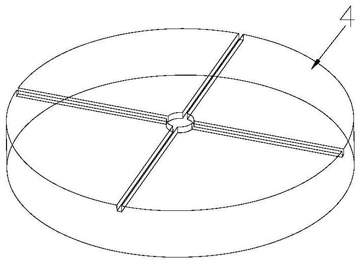
[0042] A plurality of positioning blocks 4 installed on the fixture 2 , one end of the positioning block 4 is threadedly connected with the fixture 2 , and the other end of the positioning block 4 is slidably fitted with the positioning slot 3 .

[0043] One end of the positioning block 4 of the present invention is installed on the fixture 2, and one end of the positioning block 4 can be slidably installed in the positioning groove 3 of the faceplate...


PUM


Abstract

The invention discloses a machine tool disc chuck type centering device of a tool clamp and a centering method of the machine tool disc chuck type centering device. The machine tool disc chuck type centering device comprises a machine tool disc chuck, the tool clamp borne on the machine tool disc chuck, a plurality of positioning grooves formed in the machine tool disc chuck and a plurality of positioning blocks installed on the tool clamp, wherein the positioning grooves are uniformly formed along the center of the machine tool disc chuck, one end of each positioning block is in threaded connection with the tool clamp, and the other end of each positioning block is installed in the corresponding positioning groove in a sliding fit manner. According to the machine tool disc chuck type centering device and the centering method of the machine tool disc chuck type centering device, the principle that the cross centers of two objects coincide with each other is adopted, the machine tool disc chuck and the tool clamp can be rapidly and accurately aligned, and the centering error is greatly reduced.

Description

technical field [0001] The invention relates to the technical field of positioning tooling, in particular to a faceplate-type centering device of a tooling fixture and a centering method thereof. Background technique [0002] At present, there are many jigs for rotary casing parts in aviation units, all of which are composed of a circular bottom plate and functional parts on the bottom plate. These jigs are indispensable in the manufacturing process of parts. [0003] After the workers use the crane to lift the jig to the machine tool, a very important task is to align the jig so that the center of the jig coincides with the center of rotation of the faceplate of the machine tool. However, in the process of centering, some problems were encountered. For example, the faceplate of the machine tool is a flat workbench, and the bottom plate of the fixture is also a plane. The coincidence position sometimes differs by dozens of millimeters. Fortunately, it can be placed within a...

Claims


Application Information

Patent Timeline
Patent Type & Authority Applications(China)
IPC IPC(8): B23Q3/00
CPCB23Q3/00Y02P70/10
Inventor 李福光曾浩李雪梅谭小波陈海筠
Owner AECC AERO SCI & TECH CO LTD
Why Eureka
Try Eureka