
Alignment and detection method and application of semiconductor device

A detection method and semiconductor technology, applied in the direction of instruments, measuring devices, scientific instruments, etc., can solve the problems of disordered detection results, inaccurate detection interval positions, and low reliability, so as to reduce the impact of detection, reduce focusing time, The effect of improving accuracy

Pending Publication Date: 2021-11-09
武汉人和睿视科技有限公司
View PDF0 Cites 0 Cited by
  • Summary
  • Abstract
  • Description
  • Claims
  • Application Information

AI Technical Summary

Problems solved by technology

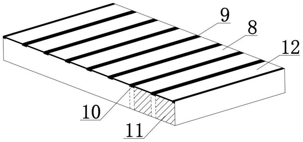
Extract the image of the side of the laser bar through sharpness detection, and then divide the detection interval of each laser single-tube light-emitting surface. Since the side features of different batches of laser bars are different, for the case where the target feature is not obvious, use the same standard to extract The characteristics lead to low reliability, so this method will cause the position of the laser single-tube light emitting surface and the actual detection interval to not correspond correctly, resulting in confusion in the detection results

Method used


Image

  • Alignment and detection method and application of semiconductor device
  • Alignment and detection method and application of semiconductor device
  • Alignment and detection method and application of semiconductor device

Examples


Embodiment 1

[0040] Such as Figure 2-4 As shown, a method for correcting a semiconductor device of the present invention comprises the following steps:

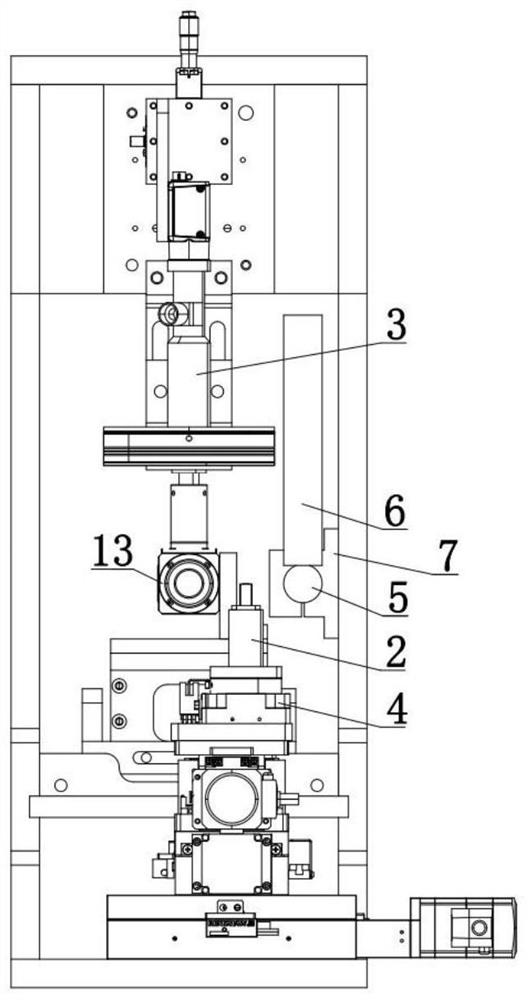
[0041] S1. Place the semiconductor device on the adsorption assembly for adsorption and fixation. The first CCD camera collects the first image information of the top surface of the semiconductor device, and the moving assembly moves the adsorption assembly according to the first image information, so that the side of the semiconductor device is positioned at the first horizontal position. Within the range of the optical displacement sensor;

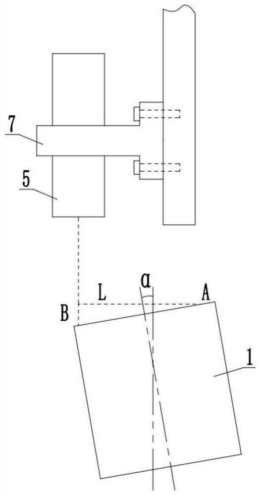
[0042] S2. The first optical displacement sensor measures the first point A from the side of the semiconductor device, the moving assembly moves a distance L along the Y axis, and the first optical displacement sensor measures the second point B from the side of the semiconductor device;

[0043] S3. According to the height difference and the distance L between the two points A and B, calculate th...


PUM


Abstract

The invention discloses an alignment and detection method and application of a semiconductor device, and the method comprises the following steps: S1, a semiconductor device is placed on an adsorption assembly for adsorption and fixation, a first CCD camera collects first image information of the top surface of the semiconductor device, a moving assembly moves the adsorption assembly according to the first image information, so that the side face of the semiconductor device is located in the measuring range of a horizontally-arranged first optical displacement sensor; S2, the first optical displacement sensor measures a first point A away from the side face of the semiconductor device, the moving assembly moves by a distance L along the Y axis, and the first optical displacement sensor measures a second point B away from the side face of the semiconductor device; s3, according to the height difference value of the points A and B and the distance L, the deflection angle alpha of the semiconductor device placed on the adsorption assembly is calculated, and the moving assembly rotates the deflection angle alpha to enable the semiconductor device to be in an orthogonal state. By means of the characteristic of high-precision distance measurement of the sensor, accurate alignment of the semiconductor device is achieved, and the method can be used for high-precision detection of the semiconductor device.

Description

technical field [0001] The invention relates to the technical field of machine vision detection of semiconductor devices, in particular to an alignment and detection method and application of semiconductor devices. Background technique [0002] With the continuous development of the semiconductor industry, this industry has become an important pillar of economic development, and the requirements for machine vision inspection of semiconductor device inspection are getting higher and higher, mainly including high-precision and high-efficiency inspection. Usually, the position of the semiconductor device needs to be corrected before testing, so that the semiconductor device is in an orthogonal state, and the direction of the field of view is perpendicular to the surface to be photographed. The current conventional method of alignment is to take the top surface image of the semiconductor device with a CCD camera According to the sharpness feature, the outer contour of the semico...

Claims


Application Information

Patent Timeline
Patent Type & Authority Applications(China)
IPC IPC(8): G01B11/26G01N21/88G01N21/01
CPCG01B11/26G01N21/88G01N21/8851G01N21/01G01N2021/8887
Inventor 饶炯辉雷畅
Owner 武汉人和睿视科技有限公司
Learn More