Pouring system and injection mold with same
A pouring system and injection mold technology, which is applied in the field of injection molds, can solve problems such as the difficulty of separating nozzle materials and plastic parts, and achieve the effect of improving production efficiency and quality, and improving production efficiency
- Summary
- Abstract
- Description
- Claims
- Application Information
AI Technical Summary
Problems solved by technology
Method used
Image

Examples
Embodiment 2
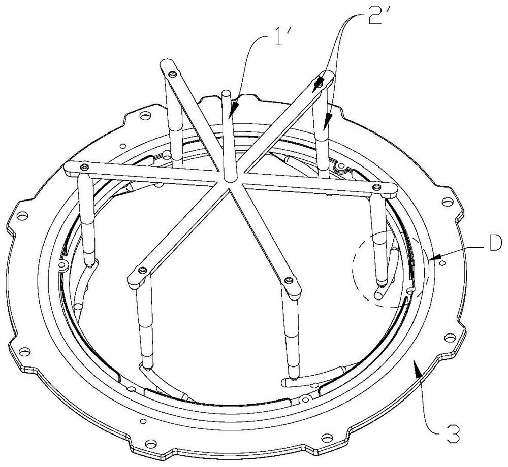
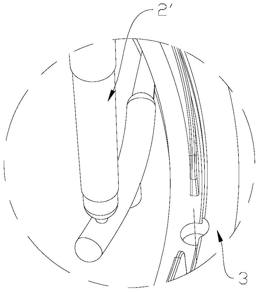
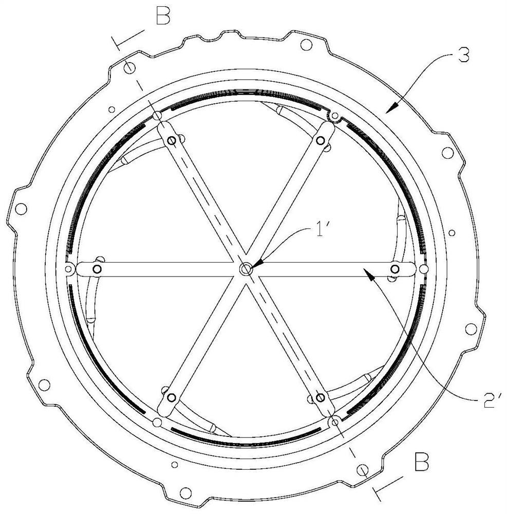
[0052] see Figure 1-Figure 4 As shown, when the gating system in the prior art cooperates with the molding system to produce injection molds, it will produce more sprue material. Specifically, as figure 1 , image 3 with Figure 4 As shown in , the sprue 1 and the runner 2, and the joints between the runner 2 and the product cavity 3 are the areas where the nozzle material is produced. The long melt flow path of the gating system with the existing structure leads to the generation of excessive nozzle material and product defects. Injection molding has a long filling cycle and low product production efficiency.
[0053] In order to solve the above problems, this embodiment is an improvement on the basis of the above embodiment 1, such as Figure 5-Figure 7 As shown, this embodiment improves the runner structure of the gating system. The runner of the gating system includes a main channel 1 and a sub-runner 2, wherein: the main channel 1 communicates with all the sub-runners...
Embodiment 3
[0068] This embodiment provides an injection mold, including a molding system and the above gating system. The molding system includes a product cavity 3 connected with the gating system.
[0069] The injection mold of this embodiment has the above-mentioned pouring system, so it also has the advantage of being able to separate the nozzle material and the product at the joint under the jacking action of the ejector system, thereby improving production efficiency.
[0070] As an optional embodiment, the injection mold further includes an ejection system for ejecting the product and / or nozzle material and a cooling system for cooling the mold.
[0071] The injection mold in this embodiment can mass-produce plastic products, mainly including four major systems;
[0072] Gating system: The feeding channel between the nozzle of the injection molding machine and the cavity becomes the gating system, which consists of the main channel 1, the runner 2 and the rubber mouth insert 4; th...
PUM
 Abstract
Description
Claims
Application Information
 - Generate Ideas
- Intellectual Property
- Life Sciences
- Materials
- Tech Scout
- Unparalleled Data Quality
- Higher Quality Content
- 60% Fewer Hallucinations
Browse by: Latest US Patents, China's latest patents, Technical Efficacy Thesaurus, Application Domain, Technology Topic, Popular Technical Reports.
© 2025 PatSnap. All rights reserved.Legal|Privacy policy|Modern Slavery Act Transparency Statement|Sitemap|About US| Contact US: help@patsnap.com