Combined base of ship lock shaft device

A combined, shaft-locking technology, applied in the transmission device of synchronous propulsion components, water action propulsion elements, climate change adaptation, etc., can solve the problem of waste of manpower and material resources, and achieve the effect of reducing modification, convenient installation and novel structure

Active Publication Date: 2020-12-18
CSSC HUANGPU WENCHONG SHIPBUILDING COMPANY
View PDF5 Cites 0 Cited by
  • Summary
  • Abstract
  • Description
  • Claims
  • Application Information

AI Technical Summary

Problems solved by technology

In the prior art, in order to ensure the continuity between the base and the original structure, a large number of modifications to the original structure are required when installing the base of the shaft locking device, resulting in a waste of manpower and material resources

Method used


Image

  • Combined base of ship lock shaft device
  • Combined base of ship lock shaft device
  • Combined base of ship lock shaft device

Examples


Embodiment Construction

[0032] The specific implementation manners of the present invention will be further described in detail below in conjunction with the accompanying drawings and embodiments. The following examples are used to illustrate the present invention, but are not intended to limit the scope of the present invention.

[0033] In describing the present invention, it should be understood that the terms "center", "longitudinal", "transverse", "length", "width", "thickness", "upper", "lower", "front", " Orientation or position indicated by "back", "left", "right", "vertical", "horizontal", "top", "bottom", "inner", "outer", "clockwise", "counterclockwise", etc. The relationship is based on the orientation or positional relationship shown in the drawings, and is only for the convenience of describing the present invention and simplifying the description, rather than indicating or implying that the referred device or element must have a specific orientation, be constructed and operated in a sp...


PUM


Abstract

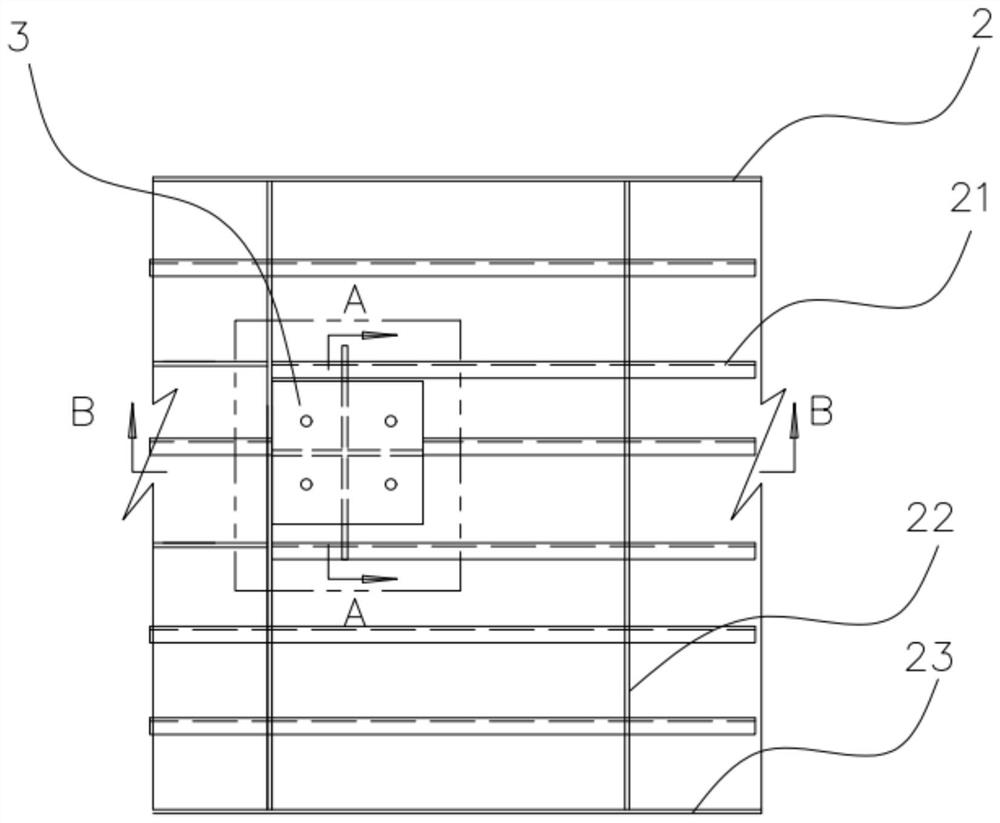
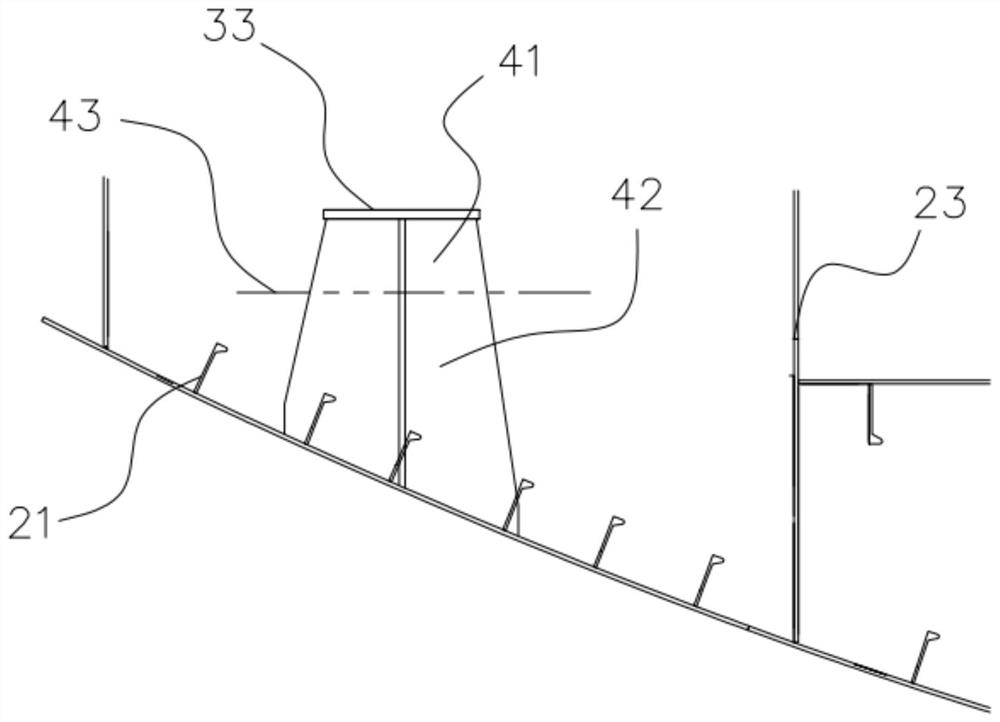
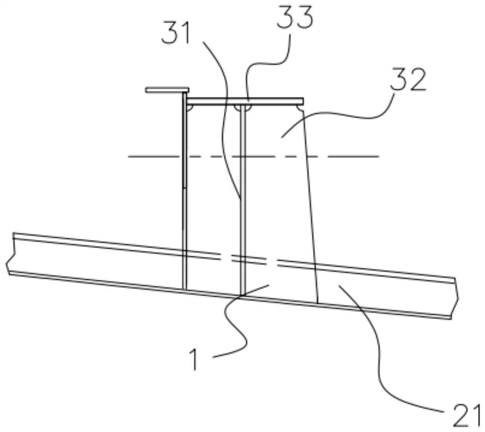
The invention relates to the technical field of ship safety devices, and discloses a combined base of a ship lock shaft device. The combined base of the ship lock shaft device comprises an upper panel, a partition plate, a first transverse web plate, a first longitudinal web plate, a second transverse web plate and a second longitudinal web plate; the upper panel is horizontal, the partition plateis arranged below the upper panel and is parallel to the upper panel, and the first transverse web plate and the first longitudinal web plate are arranged between the upper panel and the partition plate and are perpendicularly connected with the upper panel and the partition plate; the second transverse web plate and the second longitudinal web plate are arranged below the partition plate and areperpendicularly connected with the partition plate; the first transverse web plate and the first longitudinal web plate are perpendicular to each other; and the second transverse web plate and the second longitudinal web plate are perpendicular to each other. According to the combined base of the ship lock shaft device, the structure of the base is divided into the first part and the second part;the first part is the part between the partition plate and the upper panel, and the second part is the part below the partition plate; and the overall height of the base can be flexibly adjusted, thestructure is novel, the installation is convenient, and the stability is good.

Description

technical field [0001] The invention relates to the technical field of ship shaft locking devices, in particular to a combined base of a ship shaft locking device. Background technique [0002] When a ship with a propeller shaft system is running, one shaft system rotates while the other shaft system needs to stop working. [0003] The shaft locking device locks the propeller shaft when the ship is running or when the ship is stopped for maintenance to prevent the propeller shaft from following and protect the propeller and the main engine. [0004] The shaft locking device needs to be fixedly installed on the base. [0005] In the process of ship design and construction, due to the design process and related factors of equipment ordering, it is often the case that the outer dimensions of the base of the shaft locking device can only be determined according to the equipment data after the hull of the ship has started construction. In the prior art, in order to ensure the c...

Claims


Application Information

Patent Timeline
Patent Type & Authority Applications(China)
IPC IPC(8): B63H23/34
CPCB63H23/34Y02A10/30
Inventor 曾凡强黄耀华王贺郭平
Owner CSSC HUANGPU WENCHONG SHIPBUILDING COMPANY
Why Eureka
Try Eureka