Cable protective metal sleeve peeling machine

A metal sheath and stripping machine technology, applied in the direction of dismantling/armored cable equipment, etc., can solve the problems of easy damage to the cable core, high labor intensity, and inability to peel off a large length, achieving good practical value and economic benefits. The effect of improving stripping efficiency and reducing labor intensity

Active Publication Date: 2014-03-26
JIANGSU HENGTONG WIRE & CABLE TECH
View PDF4 Cites 3 Cited by
  • Summary
  • Abstract
  • Description
  • Claims
  • Application Information

AI Technical Summary

Problems solved by technology

The main problems are low efficiency, easy damage to the cable core,

Method used


Image

  • Cable protective metal sleeve peeling machine
  • Cable protective metal sleeve peeling machine
  • Cable protective metal sleeve peeling machine

Examples


Example Embodiment

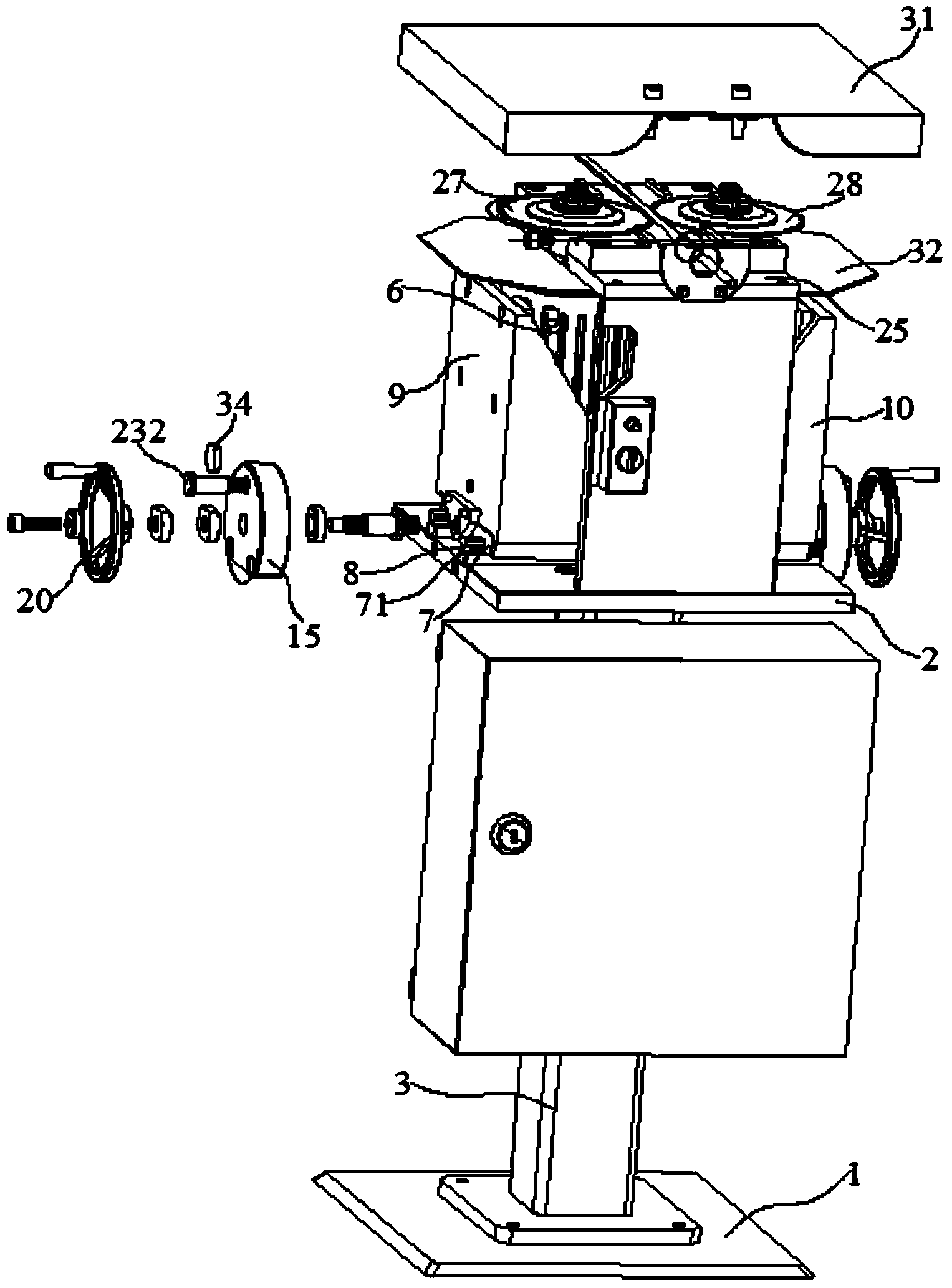
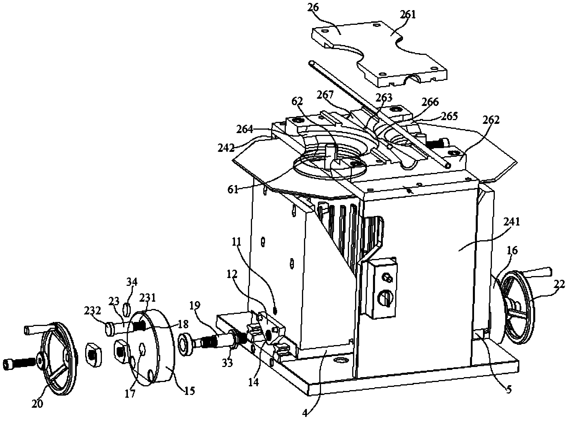
[0027] Embodiment: A cable metal sheath stripping machine, comprising: a base 1, a fixed bottom plate 2, an upright 3 fixed between the base 1, the fixed bottom plate 2, left and right motor supports 4, 5, and two motors 6 ; One of the two motors 6 is installed on the left motor bracket 4, the other is installed on the right motor bracket 5, the lower surfaces of the left and right motor brackets 4, 5 are fixed in parallel with two sliders 7, The fixed base plate 2 is provided with two linear rails 8 in parallel, and the linear rails 8 are sequentially embedded in the grooves 71 of the respective sliders 7 of the left and right motor supports 4 and 5, and the left and right motor supports 4, 5 Left and right baffles 9 and 10 with adjusting screw holes 11 are respectively fixed on the outer sides, and left and right connecting plates 12 and 13 with driving screw holes 14 are respectively fixed on the outer sides of the left and right baffles 9, 10 , The left and right connecting...


PUM


Abstract

The invention discloses a cable protective metal sleeve peeling machine. The cable protective metal sleeve peeling machine comprises a base, a fixed bottom plate, a stand column fixed between the base and the fixed bottom plate, a left motor support, a right motor support and two motors. One of the two motors is installed on the left motor support, and the other motor is installed on the right motor support. Two sliding blocks are fixed to the lower surface of the left motor support in parallel, and two sliding blocks are fixed to the lower surface of the right motor support in parallel. Two linear rails are arranged on the fixed bottom plate in parallel. The linear rails are sequentially embedded into grooves of the sliding blocks of the left motor support and grooves of the sliding blocks of the right motor support respectively. A left baffle with an adjusting screw hole and a right baffle with an adjusting screw hole are fixed to the outer side of the left motor support and the outer side of the right motor support respectively. A left connecting plate with a driving screw hole and a right connecting plate with a driving screw hole are fixed to the outer side of the left baffle and the outer side of the right baffle respectively. The left connecting plate and the right connecting plate are located between the two linear rails, and the driving screw holes are located below the left motor support and the right motor support respectively. According to the cable protective metal sleeve peeling machine, the problem that protective metal layers are difficult to cut and peel in the metal sleeve cable detection, connection and installation processes is solved, the peeling efficiency is improved, and the long protective metal layers are peeled.

Description

technical field [0001] The invention relates to a cable processing device, in particular to a cable metal sheath stripping machine. Background technique [0002] In order to meet the requirements of electromagnetic field shielding and anti-mechanical damage in various complex environments, wire and cable are equipped with copper, aluminum, steel and other metal materials or their alloys in the product design and manufacturing process. The metal shielding sheath composed of materials, that is, the cable metal sheath (also known as the metal sheath), the metal sheath is wrapped with various metal strips, longitudinally wrapped, welded into a tubular or thin round wire wrapped and other structures The form is set on the outer layer of the cable core. For cables with such a metal sheath, in the process of manufacture, installation and maintenance, the metal sheath needs to be cut and stripped before the cable core is inspected, spliced ​​and installed. Due to the existence of ...

Claims


Application Information

Patent Timeline
IPC IPC(8): H02G1/12
Inventor 余建朝王国权沈建新李宁范建华孙明华曹卫忠刘党荣
Owner JIANGSU HENGTONG WIRE & CABLE TECH
Why Eureka
Try Eureka