Comfortable handheld vibrator convenient to operate

A vibrator and comfort technology, which is applied in the field of comfortable hand-held vibrators, can solve the problems of inconvenient use of hand-held vibrators, achieve the effects of ensuring the vibration effect and improving the sense of use

Active Publication Date: 2020-12-18
新昌县籍服机械有限公司
View PDF10 Cites 2 Cited by
  • Summary
  • Abstract
  • Description
  • Claims
  • Application Information

AI Technical Summary

Problems solved by technology

[0005] The purpose of the present invention is to solve the problem that most traditional hand-held vibrators are inconvenient to use, and provide a comfortable hand-held vibrator that can effectively alleviate the inconvenience of workers' operation.

Method used


Image

  • Comfortable handheld vibrator convenient to operate
  • Comfortable handheld vibrator convenient to operate
  • Comfortable handheld vibrator convenient to operate

Examples


Embodiment 1

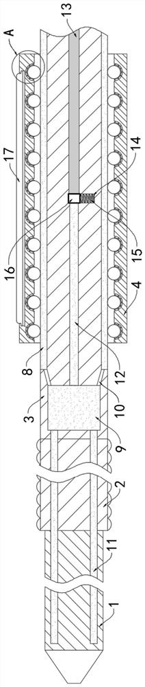
[0022] Such as Figure 1-2 As shown, a comfortable handheld vibrator that is easy to operate includes a vibrating bar 1, a flexible bar 2 and a hand-held bar 3, and the flexible bar 2 is fixedly connected between the vibrating bar 1 and the hand-held bar 3. The above is the prior art. I won't go into too much detail here.

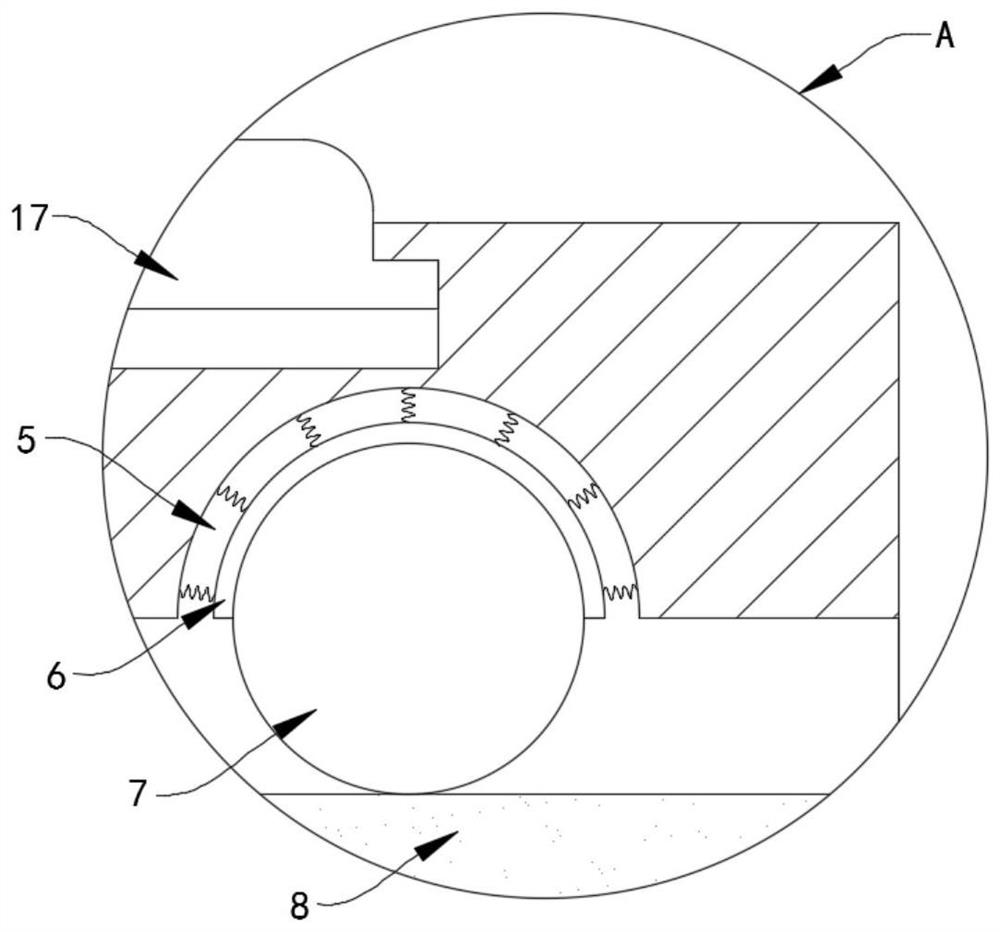
[0023] The outer coaxial sleeve of the handheld rod 3 is provided with a sliding cylinder 4, and the inner wall of the sliding cylinder 4 is provided with a plurality of evenly arranged grooves 5, and each groove 5 is fixedly connected with a hemispherical cover 6 through a plurality of outer springs. A rolling ball 7 is installed rolling in the cover 6, and an annular bag 8 is fixedly embedded in the outer wall of the hand-held rod 3. A plurality of rolling balls 7 are all in contact with the outer surface of the annular bag 8. During use, the annular bag 8 and a plurality of outer springs will Buffering most of the vibration can not only effectively impr...

Embodiment 2

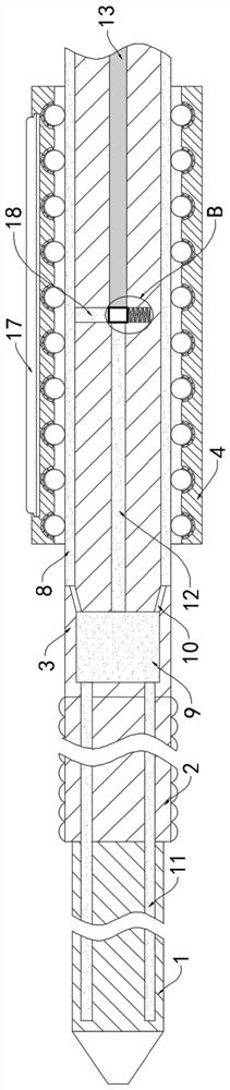
[0032] Such as Figure 3-4 As shown, the difference between this embodiment and Embodiment 1 is that: a connecting pipe 18 coaxially arranged with the sliding chamber 14 is provided in the hand-held lever 3, and the two ends of the connecting pipe 18 communicate with the annular bag 8 and the horizontal chamber 12 respectively. .

[0033] In this embodiment, when the magnetic sliding block 16 slides into the sliding cavity 14, the electrorheological fluid in the annular capsule 8 will flow into the space originally occupied by the magnetic sliding block 16 through the connecting tube 18, and the current in the annular capsule 8 The liquid change will be reduced, and the multiple rolling balls 7 will sink deeper under the elastic action of multiple outer springs on the surface of the annular bag 8. When the electrorheological fluid in the annular bag 8 is solidified, the fixing effect on the sliding cylinder 4 can be further improved. .


PUM


Abstract

The invention belongs to the field of engineering construction, and particularly relates to a comfortable handheld vibrator convenient to operate. The comfortable handheld vibrator comprises a vibrating rod, a flexible rod and a handheld rod, wherein the flexible rod is fixedly connected between the vibrating rod and the handheld rod; a sliding barrel coaxially sleeves the handheld rod; a plurality of grooves which are uniformly distributed are formed in the inner side wall of the sliding barrel; a hemispherical cover is fixedly connected in each groove through a plurality of outer springs; arolling ball is mounted in each hemispherical cover in a rolling manner; an annular bag is fixedly embedded in the outer side wall of the handheld rod; the rolling balls are in contact with the outersurface of the annular bag; and a liquid storage cavity is formed in the handheld rod. By arrangement of a centralizing mechanism, when a conductive column is connected with electrorheological fluid in a horizontal cavity, the electrorheological fluid in a plurality of communicating tubes can be changed into a solid state, the vibrating rod, the flexible rod and the handheld rod can form a whole,the position of the vibrating rod can be controlled easily through the handheld rod, the vibrating rod can be placed at a position to be machined easily, and the comfortable handheld vibrator is convenient to use.

Description

technical field [0001] The invention belongs to the field of engineering construction, and in particular relates to an easy-to-operate comfortable hand-held vibrator. Background technique [0002] Concrete vibrator includes attached vibrator and hand-held vibrator. It is a kind of equipment that uses power to generate frequent vibration through a certain device as a vibration source, and transmits this vibration to concrete to vibrate and compact concrete. Use different conditions for targeted selection. [0003] Most traditional hand-held vibrators include a vibrating rod at the front end for operation and a hand-held rod connected to the power equipment, and the vibrating rod and the handheld rod are connected by a flexible rod. When performing operations, it is difficult to accurately move the The vibrating rod is placed at a certain position for construction. It is often necessary to shake the vibrating rod to vibrate and tamp the concrete at a long distance, which is i...

Claims


Application Information

Patent Timeline
Patent Type & Authority Applications(China)
IPC IPC(8): E04G21/08
CPCE04G21/08
Inventor 强艳玲
Owner 新昌县籍服机械有限公司
Why Eureka
Try Eureka