
Gear sliding rail type electric barring device

An electric cranking and sliding rail technology, which is used in driving pumps, non-variable-capacity pumps, machines/engines, etc., can solve problems such as inconvenience in troubleshooting and troubleshooting, low efficiency, and hidden safety hazards, and improve cranking efficiency. , The effect of reducing labor intensity and convenient maintenance work

Inactive Publication Date: 2020-12-18
HEFEI AIDEWEN TECH CO LTD
View PDF0 Cites 0 Cited by
  • Summary
  • Abstract
  • Description
  • Claims
  • Application Information

AI Technical Summary

Problems solved by technology

Among them, the manual cranking device and the semi-automatic cranking device are cumbersome to operate, inefficient and have certain safety hazards
However, the existing automatic cranking device cannot realize intelligent start and stop, and once a fault occurs, the distance between the equipment and the waiting crankshaft is relatively close, which makes it very inconvenient for the staff to repair and troubleshoot the fault

Method used


Image

  • Gear sliding rail type electric barring device
  • Gear sliding rail type electric barring device
  • Gear sliding rail type electric barring device

Examples


Embodiment Construction

[0023] The following will clearly and completely describe the technical solutions in the embodiments of the present invention with reference to the accompanying drawings in the embodiments of the present invention. Obviously, the described embodiments are only some, not all, embodiments of the present invention. Based on the embodiments of the present invention, all other embodiments obtained by persons of ordinary skill in the art without making creative efforts belong to the protection scope of the present invention.

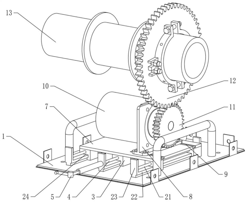
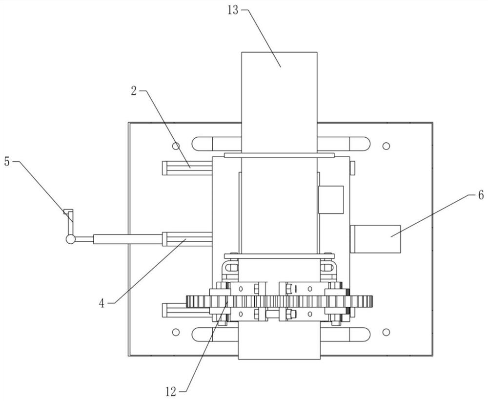
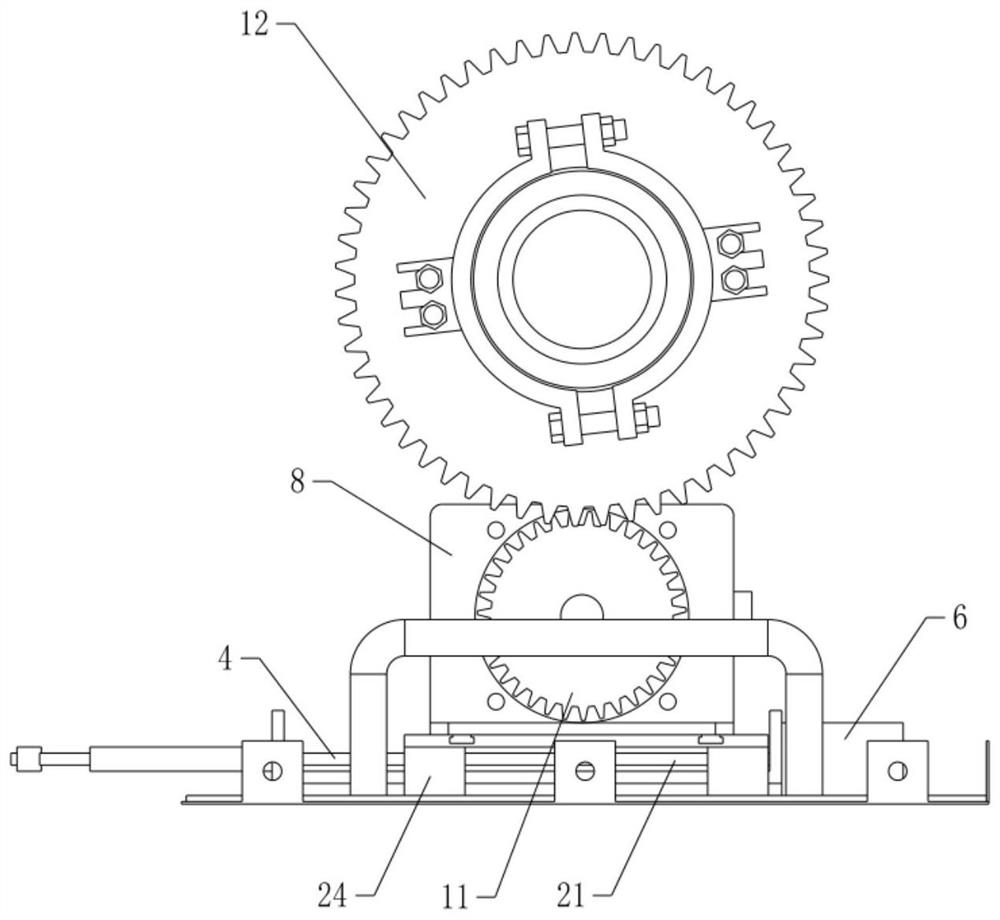
[0024] see Figure 1-4 , the present invention provides a technical solution:

[0025] A gear slide rail type electric crank, comprising

[0026] The slide rail device 2 is fixedly arranged on the base 1, the slide rail device 2 is connected to the bottom plate 7, the slide rail device 2 includes two sets of slide rails 22 fixedly arranged on both sides of the base 1, and the slide rails 22 are provided with slide bars 21 A slider 24 is movable on the slide ...


PUM


Abstract

The invention discloses a gear sliding rail type electric barring device. The gear sliding rail type electric barring device comprises a sliding rail device arranged on a base and connected with a bottom plate; sliding rails arranged on the base, wherein driving rods are arranged on the sliding rails, driving blocks in threaded connection with the driving rods are movably arranged on the sliding rails, and one ends of the driving rods are connected with a driving motor used for driving the driving rods to rotate; and the bottom plate arranged on the sliding rail device and connected with the driving blocks. By arranging a barring mechanism composed of a barring motor, a driving gear and a transmission gear, through rotation of the barring motor, a to-be-barred shaft is driven to rotate under the action of the driving gear and the transmission gear, automatic barring is achieved, the labor intensity of manual barring is greatly reduced, and the barring efficiency is improved; and meanwhile, by arranging the sliding rail device, the distance between the barring device and a main shaft can be adjusted, and convenience is brought to later maintenance work.

Description

technical field [0001] The invention relates to the technical field of barring equipment, in particular to a gear slide rail type electric barring. Background technique [0002] Before the circulating water pump unit is turned on, it is necessary to perform a cranking operation on the shaft system composed of the pump shaft, coupling and motor shaft, and observe and judge the operating status of the unit. In order to ensure the stable operation of the circulating water pump, the unit should be equipped with a turning mechanism. The turning mechanism is to turn the circulating water pump before starting to ensure the operation of the equipment. [0003] However, in the existing cranking equipment, before each water pump is turned on and off, the operator must go to the site to perform a series of manual operations, including checking the cranking to ensure that the equipment is not faulty, which is cumbersome and time-consuming. In the field of circulating water pump testing...

Claims


Application Information

Patent Timeline
Patent Type & Authority Applications(China)
IPC IPC(8): F04B17/03F04B49/02F04B53/00F04D9/00F04D13/06
CPCF04B17/03F04B49/02F04B53/00F04D9/00F04D13/06
Inventor 朱元木李跃宋艺伟朱旻鹏胡翰林柴立功范庆波
Owner HEFEI AIDEWEN TECH CO LTD
Learn More