Straight flow type ball sealing check valve and use method thereof

A technology of check valves and rubber balls, applied in valve details, valve devices, control valves, etc., can solve the problems of oblique slideway blockage, blockage of liquid flow, large resistance, etc., and achieve easy maintenance and replacement, check effect Good, fast closing effect

Active Publication Date: 2020-12-18
ZHEJIANG GUANLIN VALVE CO LTD
View PDF9 Cites 1 Cited by
  • Summary
  • Abstract
  • Description
  • Claims
  • Application Information

AI Technical Summary

Problems solved by technology

However, when the device is actually used, it is difficult to process the inclined slideway, resulting in low production efficiency and quality. In addition, when the spherical valve disc moves upward along the inclined slideway, the resistance to be overcome is relatively large, and the lifting speed of the spherical valve disc is slow. As a result, the opening speed of the channel opening is slow; in addition, the setting of the inclined slideway will also block the flow of the liquid, resulting in a certain resistance, which is not conducive to the flow of the liquid. When there are many impurities in the liquid, it is easy to form a blockage at the inclined slideway. It is inconvenient to clean, and when there are many impurities, it will also affect the self-closing and sealing of the spherical disc, which will eventually affect the water-stopping effect

Method used


Image

  • Straight flow type ball sealing check valve and use method thereof
  • Straight flow type ball sealing check valve and use method thereof
  • Straight flow type ball sealing check valve and use method thereof

Examples


Embodiment 1

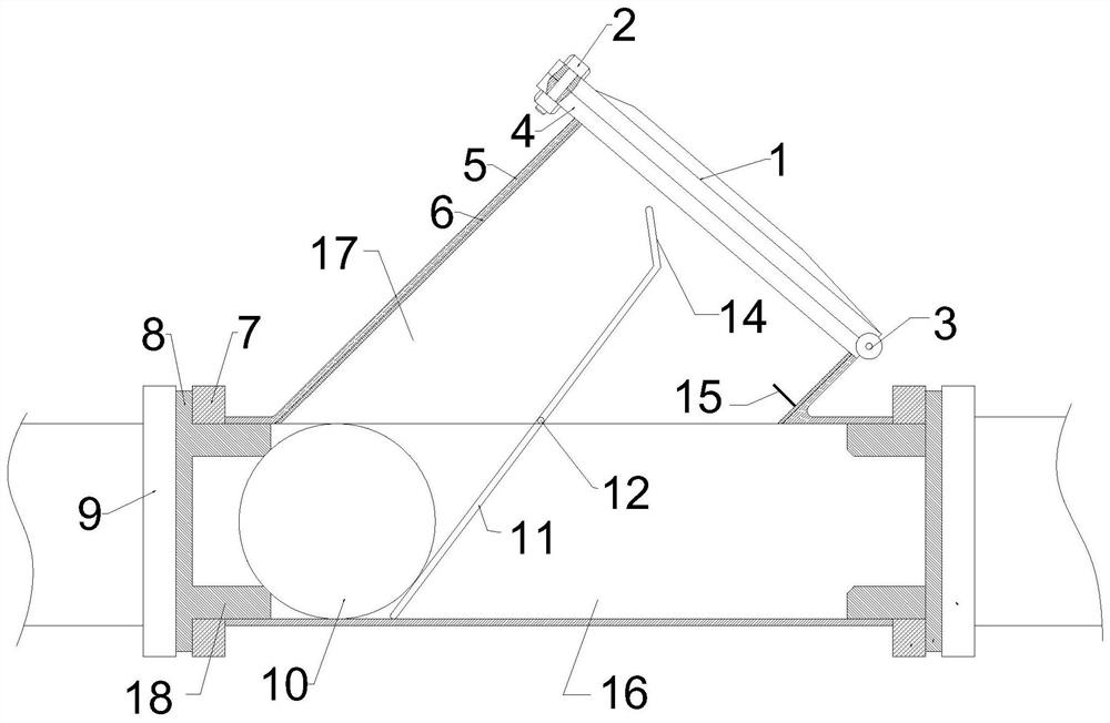
[0032] Such as Figure 1-3 ,and Image 6 As shown, a direct current type ball seal check valve proposed in this embodiment includes a valve body 5 and a rubber ball 10 arranged in the valve body 5. The valve body 5 has a three-way structure as a whole. The medium channel 16 for the liquid to enter and exit, the left end is the inlet, and the right end is the outlet. The medium channel 16 is arranged in a straight shape; It is inclined, and the valve cover 1 is detachably connected to the port of the installation passage 17. The specific structure is: the third flange piece 4 is fixedly welded at the port of the installation passage 17, and the valve cover 1 is connected to the third flange through the rotating shaft 3. The blue piece 4 is hinged, the valve cover 1 can rotate around the rotation axis 3, the valve cover 1 is fixedly connected with the third flange piece 4 through the bolt 2, and an O Type ring to improve the sealing effect.

[0033] Both ends of the valve bod...

Embodiment 2

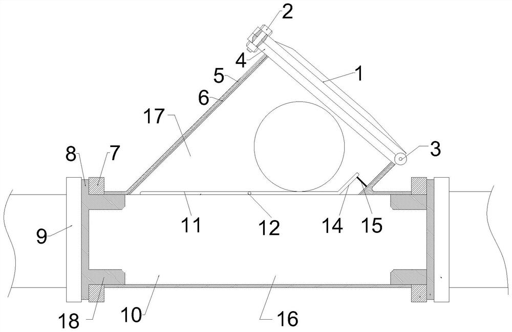
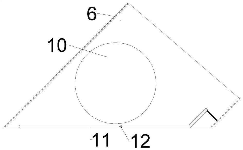
[0045] Such as Figure 4-5 As shown, on the basis of Embodiment 1, a baffle is provided on the rotating plate 11, and the baffle can be arranged at an inclination to block the rubber ball 10. When the rubber ball 10 contacts the baffle, the rubber ball The center of the sphere of 10 and the center line of bearing pin 12 are coplanarly arranged. In addition, since the surface of the rubber ball 10 is an elastic rubber layer, the water flow impacts the rubber ball 10 to make it contact with the baffle and squeeze it, deforming it and generating a certain elastic force.

[0046] The purpose of such setting is that when the liquid is pumped, the impact force of the liquid drives the rubber ball 10 to move and support on the surface of the baffle, which can drive the baffle to rotate rapidly, and then drive the rotating plate 11 to reach a horizontal state quickly, and the rotating plate 11 The right end is pressed against the limit post 15. At this time, the ball center of the ru...


PUM


Abstract

The invention discloses a straight flow type ball sealing check valve and a use method thereof. The straight flow type ball sealing check valve comprises a valve body and a rubber ball, wherein a medium passage and an installing passage are formed in the valve body; a valve cover is detachably connected to an end opening of the installing passage; the two ends of the valve body are respectively connected with a first flange piece and a second flange piece; a sealing gasket is arranged between the first flange piece and the second flange piece; an annular extending part is arranged on the sealing gasket; the extending part is tightly attached to the inner wall of the medium passage and extends into the medium passage; a sleeve-shaped valve element is detachably connected into the installingpassage; a rotating plate is also arranged in the valve body; the rotating plate is connected with the valve element in a relatively rotating mode through a pin shaft; the right end of the rotating plate is connected with a side plate which tilts upwards; and a position limiting post is arranged on the inner wall of the valve element, and jacks and supports the bottom surface of the side plate torealize the position limitation of the rotating plate. The straight flow type ball sealing check valve has the advantages that the structure is simple; mounting and dismounting are convenient; lifting and falling of the rubber ball can be rapidly assisted through the rotation of the rotating plate; the opening and closing speed of the medium passage is high; and the non-return effect is good.

Description

technical field [0001] The invention relates to the technical field of valves, in particular to a direct-flow type ball-sealed check valve and a use method thereof. Background technique [0002] The ball check valve is a lifting check valve with multi-ball, multi-channel, multi-cone type inverted fluid structure. The spherical device is composed of a ball cover and a rubber ball. Layer, maintain a certain degree of elasticity and sufficient strength. The working principle is that the rubber ball rolls in a short stroke in the ball cover to realize the opening and closing of the valve. When the water pump starts, the pressure of the water pushes away the rubber ball, causing the rubber ball to roll to the right, and the check valve opens; after the pump is stopped, due to the return water pressure of the system, the rubber ball is forced to roll to the left, and the check valve is closed. After searching, the utility model patent with the authorized announcement number CN20...

Claims


Application Information

Patent Timeline
Patent Type & Authority Applications(China)
IPC IPC(8): F16K15/04F16K27/02F16K27/08
CPCF16K15/04F16K27/0209F16K27/0245F16K27/08
Inventor 李贤明李亚鹏李红佳
Owner ZHEJIANG GUANLIN VALVE CO LTD
Why Eureka
Try Eureka