Heat dissipation and shock absorption protection device for gas equipment

A protection device and equipment heat dissipation technology, applied in valve devices, mechanical equipment, household refrigeration devices, etc., can solve problems such as equipment cannot automatically open emergency shut-off valve, gas equipment leakage, etc., to improve the safety of use and avoid excessive temperature. High, the effect of expanding the heat dissipation range

Inactive Publication Date: 2020-12-18
WENZHOU LUXI INTELLIGENT TECH CO LTD
View PDF0 Cites 1 Cited by
  • Summary
  • Abstract
  • Description
  • Claims
  • Application Information

AI Technical Summary

Problems solved by technology

[0002] Gas equipment is an important facility to ensure reliable gas supply in cities. It is equipped with flammable media, which are prone to explosion when the temperature is too high. When gas equipment is used, the equipment will generate a large amount of heat, which needs to be dissipated in time. At the same time, gas equipment is easy to In the event of gas leakage, the gas equipment must be installed with an emergency shut-off valve. When there is a failure such as a rupture in the external pipeline, the staff needs to close the emergency shut-off valve. At the same time, if no staff is present, the equipment cannot automatically open the emergency shut-off valve, so that accidents occur, a heat dissipation and shock absorption protection device for gas equipment explained in the present invention can solve the above problems

Method used


Image

  • Heat dissipation and shock absorption protection device for gas equipment
  • Heat dissipation and shock absorption protection device for gas equipment
  • Heat dissipation and shock absorption protection device for gas equipment

Examples


Embodiment Construction

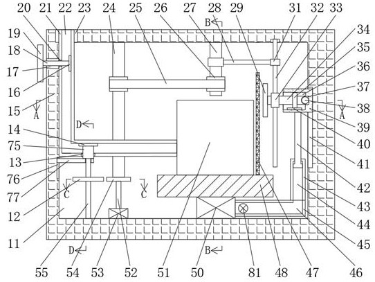
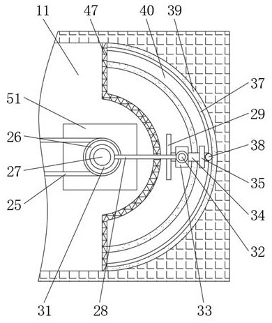
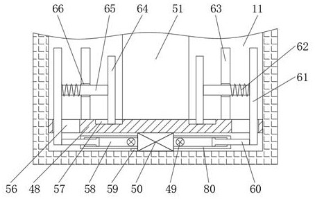
[0016] Combine below Figure 1-Figure 5 The present invention is described in detail, and for convenience of description, the orientations mentioned below are now stipulated as follows: figure 1 The up, down, left, right, front and back directions of the projection relationship itself are the same.

[0017]A heat dissipation and shock absorption protection device for gas equipment according to the present invention includes a base 15, an inner cavity 11 is arranged inside the base 15, and an outlet hole 23 with an upward opening is communicated with the upper wall of the inner cavity 11, and the inner cavity 11, the left wall communicates with a through hole 17 opening to the left, a support plate 48 is connected between the front and rear walls of the inner cavity 11, and a protective net 47 is fixedly connected to the upper right side of the support plate 48, and the front and rear ends of the protective net 47 They are fixedly connected to the front and rear walls of the i...


PUM


Abstract

The invention discloses a heat dissipation and shock absorption protection device for gas equipment. The heat dissipation and shock absorption protection device comprises a base, wherein an inner cavity is formed in the base; an outlet hole with an upward opening communicates with an upper wall of the inner cavity; a through hole with a leftward opening communicates with a left wall of the inner cavity; a support plate is connected between a front wall and a rear wall of the inner cavity; a protection net is fixedly connected to the upper end of the right side of the support plate; and the front end and the rear end of the protection net are fixedly connected to the front wall and the rear wall of the inner cavity separately. According to the heat dissipation and shock absorption protection device, through indirect cooperation of a cooling fan and a rack and indirect cooperation of a rotating shaft and a ball, sufficient heat dissipation treatment is carried out on the gas equipment, meanwhile, the heat dissipation range is enlarged, and too high temperature of a gas medium in the equipment is avoided, so that an accident source is cut off; meanwhile, through indirect cooperation of shock absorbing springs and shock absorbing plates, shock absorbing treatment is carried on the gas equipment in work, so that the damage to the gas equipment caused by vibration is prevented; and through the arrangement of two emergency cut-off valves, the emergency cut-off valves are indirectly and automatically controlled to be closed through a driving gear, so that the use safety of the gasequipment is improved.

Description

technical field [0001] The invention relates to the related fields of gas equipment, in particular to a heat dissipation and shock absorption protection device for gas equipment. Background technique [0002] Gas equipment is an important facility to ensure reliable gas supply in cities. It is equipped with flammable media, which are prone to explosion when the temperature is too high. When gas equipment is used, the equipment will generate a large amount of heat, which needs to be dissipated in time. At the same time, gas equipment is easy to In the event of gas leakage, the gas equipment must be installed with an emergency shut-off valve. When there is a failure such as a rupture in the external pipeline, the staff needs to close the emergency shut-off valve. At the same time, if no staff is present, the equipment cannot automatically open the emergency shut-off valve, thus accidents occur, and a heat dissipation and shock absorption protection device for gas equipment exp...

Claims


Application Information

Patent Timeline
Patent Type & Authority Applications(China)
IPC IPC(8): F17D1/04F17D5/00F17D5/06F16L55/07F16K31/06F16K37/00F16F15/02F16F15/067F25D1/00F25D17/06
CPCF16F15/02F16F15/067F16K31/0668F16K37/0091F16L55/07F17D1/04F17D5/005F17D5/06F25D1/00F25D17/06
Inventor 朱成美
Owner WENZHOU LUXI INTELLIGENT TECH CO LTD
Why Eureka
Try Eureka