Electronic component aging test seat and aging test device comprising same

A technology for electronic components and aging testing, which is applied to measuring devices, measuring device casings, and optical devices, etc. It can solve the problems of cumbersome operation, low efficiency, and inconvenient installation of aging test sockets for TR components, so as to improve accuracy and efficiency. Effect

Pending Publication Date: 2020-12-18
BEIJING INST OF RADIO MEASUREMENT
View PDF13 Cites 0 Cited by
  • Summary
  • Abstract
  • Description
  • Claims
  • Application Information

AI Technical Summary

Problems solved by technology

[0002] Aging test can improve the reliability of TR components. During the aging process, TR components are overloaded to make defects appear in a short time, so as to avoid failure of TR components in the early stage of use; at present, before the aging test of TR components, it is necessary to test The personnel installs the TR assembly on the aging test frame, and then connects the TR assembly with the aging test instrument through the test personnel, and then conducts the aging test by powering on; however, the aging test seat provided on the existing aging test frame is generally fixed, and it is not convenient to install The TR assembly is installed on the burn-in test socket; moreover, to connect the TR assembly with the burn-in test instrument on the existing burn-in test stand, it is necessary to connect the burn-in test instrument to the input and output ends of the TR assembly one by one, which is cumbersome and cumbersome to operate. low efficiency
In addition, in the prior art, there are also the above-mentioned problems when other electronic components similar to TR components are installed on the aging test frame

Method used


Image

  • Electronic component aging test seat and aging test device comprising same
  • Electronic component aging test seat and aging test device comprising same
  • Electronic component aging test seat and aging test device comprising same

Examples


Embodiment Construction

[0055] In order to make the purpose, technical solution and advantages of the present application clearer, the implementation manners of the present application will be further described in detail below in conjunction with the accompanying drawings.

[0056] In order to understand the above-mentioned purpose, features and advantages of the present invention more clearly, the present invention will be further described in detail below in conjunction with the accompanying drawings and specific embodiments. It should be noted that, in the case of no conflict, the embodiments of the present application and the features in the embodiments can be combined with each other.

[0057] In the following description, many specific details are set forth in order to fully understand the present invention. However, the present invention can also be implemented in other ways different from those described here. Therefore, the protection scope of the present invention is not limited by the speci...


PUM


Abstract

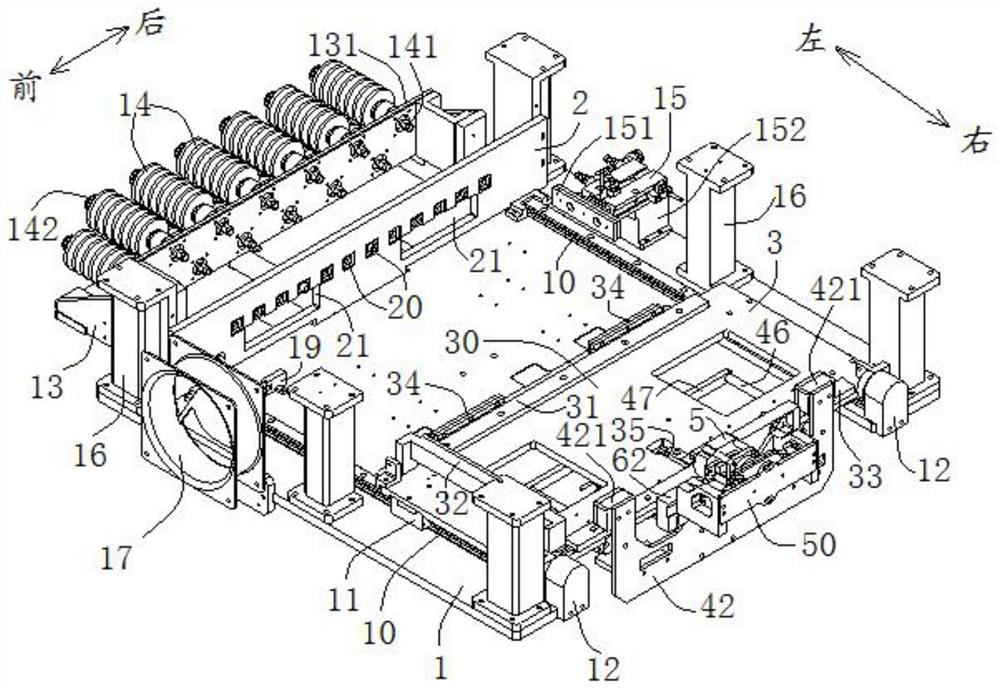
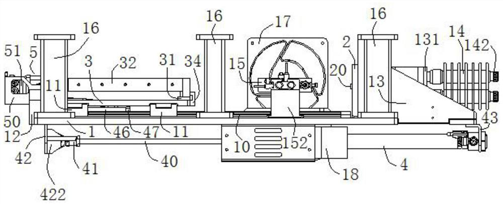
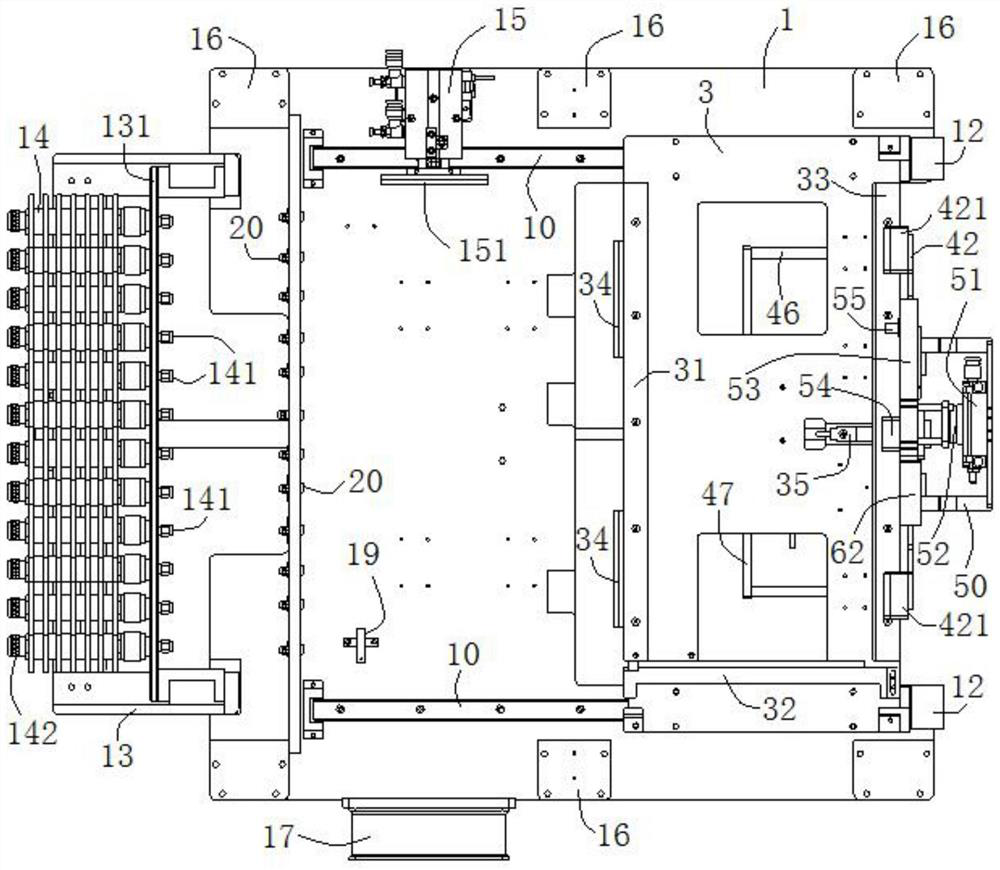
The invention discloses an electronic component aging test seat and an aging test device comprising the same, and belongs to the technical field of electronic product testing. The electronic assemblyis provided with an input end and an output end, and the electronic assembly aging test seat comprises a base; a mounting base mounted on the base in a sliding manner, and a mounting cavity is formedin the mounting base; a test output butt joint seat which is connected to the base, and an output butt joint plug is arranged on the test output butt joint seat; a telescopic mechanism I, one end of the telescopic mechanism I is connected to the base, and the other end is connected with the mounting base; a test input butt-joint seat which is arranged on the base in a manner of directly facing thetest output butt-joint seat and is positioned on one side of the mounting seat, a test input butt-joint plug is arranged on the test input butt-joint seat in a manner of directly facing the input end, and the test input butt-joint plug is electrically connected with the signal source; and a telescopic mechanism II, one end of the telescopic mechanism II is connected to the mounting seat, and theother end is connected with the test input butt joint seat. According to the electronic component aging test seat, the electronic component is convenient to install, and the connection efficiency of the electronic component and the aging test instrument is improved.

Description

technical field [0001] The invention relates to the technical field of electronic product testing, in particular to an aging test seat for electronic components and an aging test device containing the same. Background technique [0002] Aging test can improve the reliability of TR components. During the aging process, TR components are overloaded to make defects appear in a short time, so as to avoid failure of TR components in the early stage of use; at present, before the aging test of TR components, it is necessary to test The personnel installs the TR assembly on the aging test frame, and then connects the TR assembly with the aging test instrument through the test personnel, and then conducts the aging test by powering on; however, the aging test seat provided on the existing aging test frame is generally fixed, and it is not convenient to install The TR assembly is installed on the burn-in test socket; moreover, to connect the TR assembly with the burn-in test instrume...

Claims


Application Information

Patent Timeline
Patent Type & Authority Applications(China)
IPC IPC(8): G01R31/00G01R1/04G01B11/00
CPCG01R31/003G01R1/0408G01R1/04G01B11/00
Inventor 冯吉祥张奇勋侯佳赞李世华刘冬冬王智慧韩策卢子琦
Owner BEIJING INST OF RADIO MEASUREMENT
Why Eureka
Try Eureka