Double-chamber arc extinguishing chamber

An arc extinguishing chamber and double-chamber technology, applied in high-voltage air circuit breakers, electrical components, electrical switches, etc., can solve problems such as ablation of conductive connecting parts, and achieve safety assurance, flexible design and layout, and safety assurance Effect

Inactive Publication Date: 2020-12-18
PINGGAO GRP +2
View PDF9 Cites 0 Cited by
  • Summary
  • Abstract
  • Description
  • Claims
  • Application Information

AI Technical Summary

Problems solved by technology

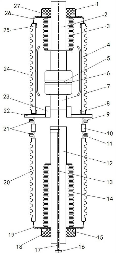
[0006] The purpose of the present invention is to provide a double-chamber arc extinguishing chamber to solve the problem that the two chambers of the existing arc extinguishing chamber are connected and disconnected at the same time, resulting in the generation of arcs in both chambers at the same time, which in turn causes the two chambers to be disconnected. The corresponding conductive connection parts in the chamber are simultaneously subjected to the problem of arc ablation

Method used


Image

  • Double-chamber arc extinguishing chamber
  • Double-chamber arc extinguishing chamber
  • Double-chamber arc extinguishing chamber

Examples


Embodiment Construction

[0032] In order to make the object, technical solution and advantages of the present invention clearer, the present invention will be further described in detail below in conjunction with the accompanying drawings and embodiments. It should be understood that the specific embodiments described here are only used to explain the present invention, and are not intended to limit the present invention, that is, the described embodiments are only some of the embodiments of the present invention, but not all of the embodiments. The components of the embodiments of the invention generally described and illustrated in the figures herein may be arranged and designed in a variety of different configurations.

[0033] Accordingly, the following detailed description of the embodiments of the invention provided in the accompanying drawings is not intended to limit the scope of the claimed invention, but merely represents selected embodiments of the invention. Based on the embodiments of the...


PUM


Abstract

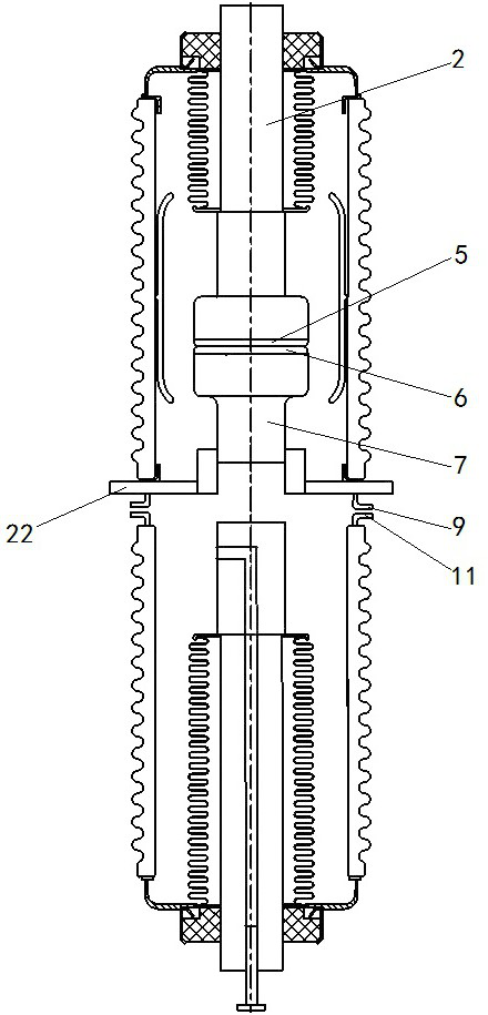
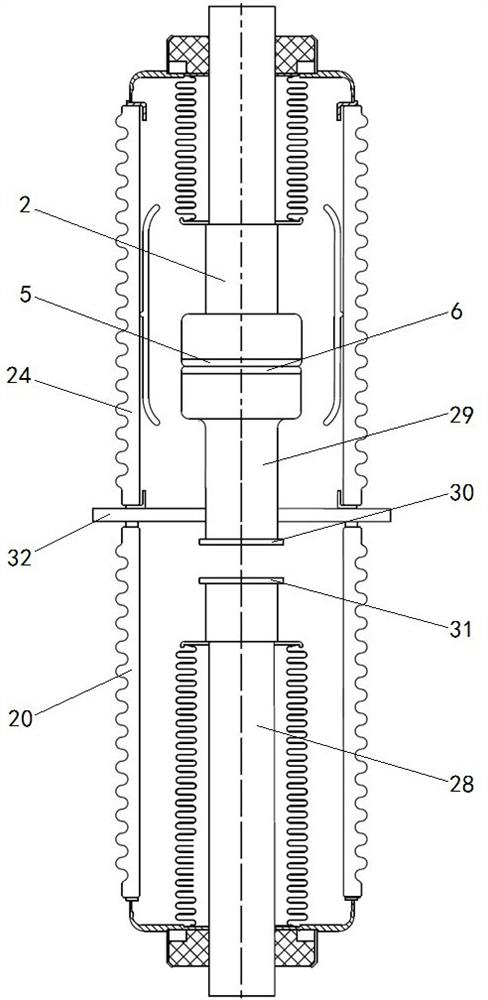
The invention provides a double-chamber arc extinguishing chamber. The double-chamber arc extinguishing chamber comprises a first cylinder, and a first moving conducting rod, and a first moving contact which is fixed at the end part, extending into the first cylinder, of the first moving conducting rod; the double-chamber arc extinguishing chamber further comprises a second cylinder, and asecond moving conducting rod, and one end of the second moving conducting rod extends into the second cylinder; the double-chamber arc extinguishing chamber further comprises a middle separator which is fixedly connected with the first cylinder and the second cylinder , the middle separator is provided with a first static contact used for being in butt joint with the first moving contact for conduction ordisconnection, and the middle separator is further provided with a conductive connection structure in conductive connection with or disconnected from the second moving conducting rod; the first cylinder and the second cylinder are separated into a first chamber and a second chamber which are independent from each other by the middle separator, and the first chamber is a vacuum chamber; during use, the first moving contact and the first static contact are disconnected firstly to realize on-off of the double-chamber arc extinguishing chamber, and then the second moving conducting rod and the conductive connection structure are disconnected to realize isolation of the double-chamber arc extinguishing chamber. The beneficial effects are that electric arcs are prevented from being generated inthe two chambers at the same time, so that the problem that corresponding conductive connecting parts in the two chambers bear electric arc ablation at the same time is solved.

Description

technical field [0001] The invention relates to the technical field of components for power transmission and distribution switchgear, in particular to a double-chamber arc extinguishing chamber. Background technique [0002] The vacuum interrupter is an important part of the vacuum circuit breaker. Most of the existing vacuum interrupters have a single-fracture structure. The single-fracture can be used as a breaking fracture or an isolation fracture. Obvious problem. Therefore, a separate isolating switch is generally added outside the arc extinguishing chamber. The isolating switch is positioned as a mechanical operating device that only provides the isolation distance at the opening position according to special requirements. At present, the isolating switch is usually required to have a visible isolating fracture to ensure isolation. Reliability, but the distribution network switchgear continues to develop toward integration and miniaturization, and the disadvantages of...

Claims


Application Information

Patent Timeline
Patent Type & Authority Applications(China)
IPC IPC(8): H01H33/664
CPCH01H33/664
Inventor 齐大翠亓春伟李小钊刘畅刘世柏薛从军赵芳帅李锟张杨王宇浩海俊超王茜
Owner PINGGAO GRP
Why Eureka
Try Eureka