Buried pipe pay-off device for water conservancy project

A wire-laying device and water conservancy engineering technology, which is applied in the direction of cable installation device, cable installation, electrical components, etc., can solve the problems that the pipeline cannot be moved forward, the buried pipe cannot be completed, and the work efficiency is low, so as to achieve the design idea Clear, small footprint, simple structure effect

Active Publication Date: 2020-12-18
YELLOW RIVER CONSERVANCY TECHN INST
View PDF7 Cites 10 Cited by
  • Summary
  • Abstract
  • Description
  • Claims
  • Application Information

AI Technical Summary

Problems solved by technology

[0005] In view of the above situation, in order to overcome the defects of the prior art, the present invention provides a buried pipe pay-off device for water conservancy projects, which effectively solves the problem that the existing buried pipe pay-off method not only has low work efficiency, but also can cause problems when the cable is too long. When the pipe is bent, it is easy to bend in the pipe and cannot move forward in the pipe; if there is a foreign object in the buried pipe, it will not be possible to complete the work of laying out the buried pipe

Method used


Image

  • Buried pipe pay-off device for water conservancy project
  • Buried pipe pay-off device for water conservancy project
  • Buried pipe pay-off device for water conservancy project

Examples


Embodiment 1

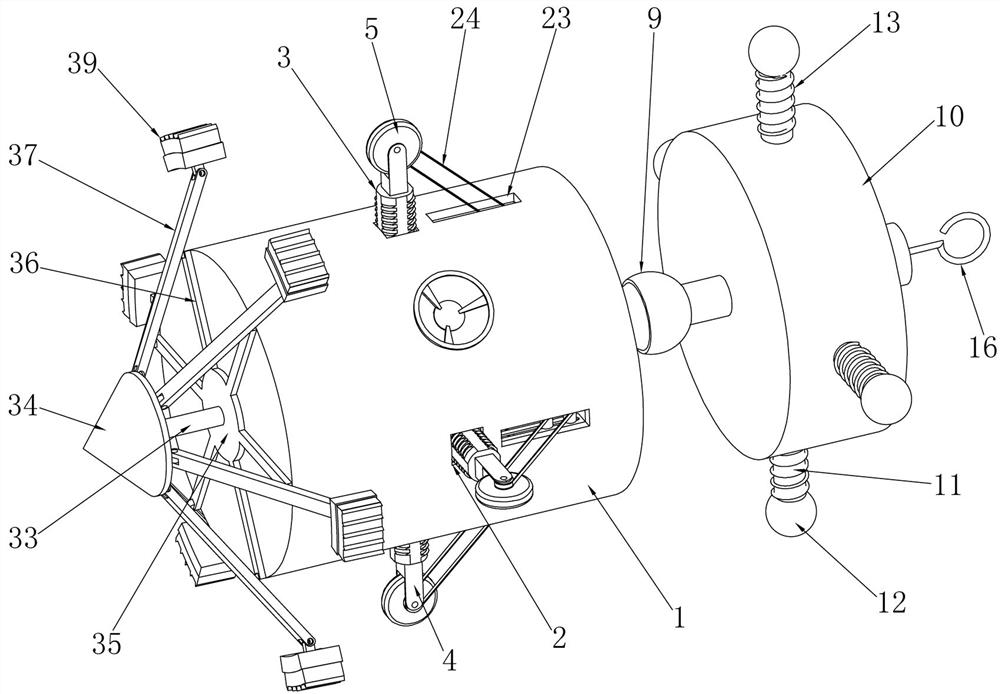
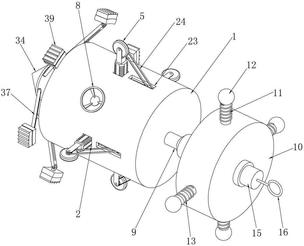
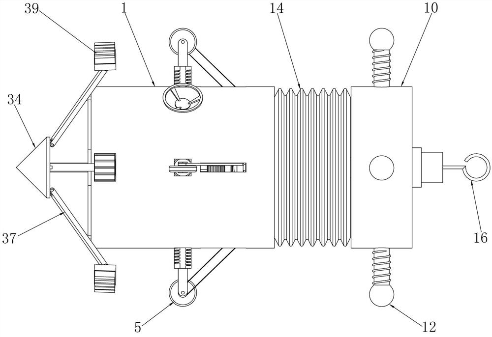
[0034] Embodiment 1, the present invention is a buried pipe pay-off device for water conservancy projects, which includes an outer cylinder 1 with closed left and right ends, and the outer cylinder 1 provides a fixed foundation for the subsequent structure. It is characterized in that the outer cylinder 1 Square adjustment holes 2 are respectively opened on the front, rear, upper and lower sides, and the four adjustment holes 2 respectively pass through the side wall of the outer cylinder 1, and a square adjustment screw rod 3 is slidingly installed in the four adjustment holes 2, respectively. The screw rods 3 can slide radially around in the adjusting cylinder 2 at the same time. When the four adjusting screw rods 3 slide outward, the distance between the four adjusting screw rods 3 becomes larger, that is, the axis of the outer cylinder 1 to the adjusting screw rods 3 The distance from the top of the top is the radius. When the adjustment screw 3 slides, the radius changes a...

Embodiment 2

[0037] Embodiment 2. On the basis of Embodiment 1, square telescopic holes 17 are respectively opened at the ends of the four adjustment screw rods 3 located outside the outer cylinder 1. The cross-sections of the four walking wheel shafts 4 are square and respectively Slidingly installed in the four telescopic holes 17, the telescopic springs 18 between the walking wheel shaft 4 and the telescopic holes 7 are installed respectively in the four telescopic holes 17, when the positions of the four adjusting screw mandrels 3 are adjusted, the four When a walking wheel 5 drives the outer cylinder 1 to walk in the buried pipe, if there is a protrusion or foreign matter on the inner wall of the pipe, the walking wheel shaft 4 can slide into the telescopic hole 17 and compress the telescopic spring 18. When passing through the protrusion or foreign matter Under the action of the telescopic spring 18, the traveling wheel shaft 4 slides outwards, so that the traveling wheel 5 walks clos...

Embodiment 3

[0038] Embodiment 3. On the basis of Embodiment 1, the traveling wheel drive device includes a fixed plate 19 fixedly installed on the inner wall on the right side of the outer cylinder 1. The fixed plate 19 is installed coaxially with the outer cylinder 1, and is connected to the outer cylinder 1. There is a certain gap in the right inner wall of the fixed plate 19, and four driving worm gears 20 on the same side of the four road wheels 5 are installed on the left side of the fixed plate 19, and four driving worm gears 20 are coaxially installed respectively. Driving pulley 21, driving worm wheel 20 can rotate synchronously with driving pulley 21, four described traveling wheels 5 are respectively coaxially equipped with driving pulley 22, traveling wheel 5 and driving pulley 22 can rotate synchronously, the outer tube 1 There are transmission grooves 23 on the front, rear, upper and lower sides respectively. Four transmission grooves 23 run through the side wall of the outer ...


PUM


Abstract

The invention provides a buried pipe pay-off device for a water conservancy project. The buried pipe pay-off device solves the problems that an existing buried pipe pay-off method is low in working efficiency, and when a cable is too long, the cable is prone to bending in a pipeline and cannot move forwards. The device comprises an outer cylinder, square adjusting holes are formed in the front side, the rear side, the upper side and the lower side of the outer cylinder correspondingly, adjusting lead screws are slidably arranged in the four adjusting holes correspondingly, walking wheel shaftsare fixed to the ends, located on the outer side of the outer cylinder, of the four adjusting lead screws correspondingly, and walking wheels are rotationally arranged at the other ends of the four walking wheel shafts correspondingly; outer tooth internal thread bushings which are coaxial with the four adjusting lead screws and are in threaded fit with the four adjusting lead screws are rotationally installed on the inner wall of the outer barrel, an adjusting gear ring meshed with the four outer tooth internal thread bushings at the same time is coaxially and rotationally installed in the outer barrel, and an adjusting driving gear meshed with the adjusting gear ring is rotationally installed on the inner wall of the outer barrel. A mechanical automatic transmission device is adopted, so that automation of buried pipe pay-off work is achieved, the working efficiency is improved, and the problem that a cable is stopped in a pipeline is solved.

Description

technical field [0001] The invention relates to the technical field of water conservancy engineering, in particular to a buried pipe setting-out device for water conservancy engineering. Background technique [0002] Water conservancy engineering is a project built to control and allocate natural surface water and groundwater to achieve the purpose of eliminating harm and rejuvenating benefits, also known as water engineering; water is an indispensable precious resource for human production and life, but its natural existence The state does not fully meet the needs of human beings. Only by building water conservancy projects can water flow be controlled, floods prevented, and water volume adjusted and distributed to meet the needs of people's life and production for water resources. Water conservancy projects require the construction of dams, dikes, Spillways, sluices, water intakes, channels, aqueducts, raftways, fishways and other different types of hydraulic structures to...

Claims


Application Information

Patent Timeline
IPC IPC(8): H02G1/08
CPCH02G1/088
Inventor 雷恒李颖聂松广万晓丹曹明伟曹永娣高新江马晓慧
Owner YELLOW RIVER CONSERVANCY TECHN INST
Why Eureka
Try Eureka