A buried pipe laying-out device for water conservancy projects
A technology of pay-off device and water conservancy project, which is applied in the direction of cable installation device, cable installation, electrical components, etc., can solve the problems such as the inability to move the pipeline forward, the inability to complete the lay-out of the buried pipe, and the low work efficiency, and achieve the design idea. Clear, small footprint, and simple structure
- Summary
- Abstract
- Description
- Claims
- Application Information
AI Technical Summary
Problems solved by technology
Method used
Image

Examples
Embodiment 1
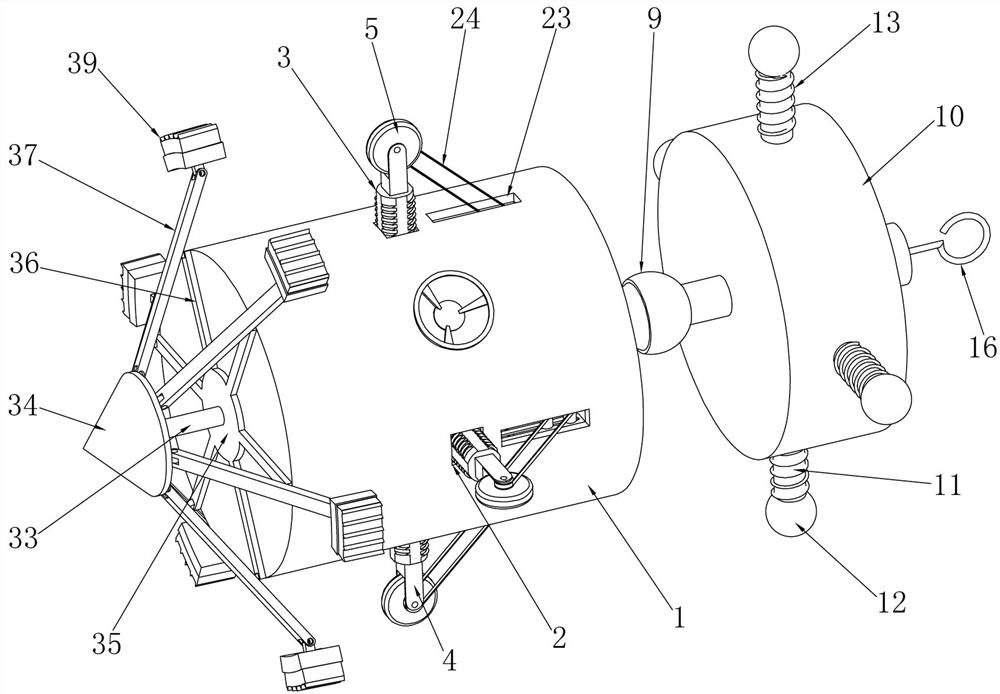
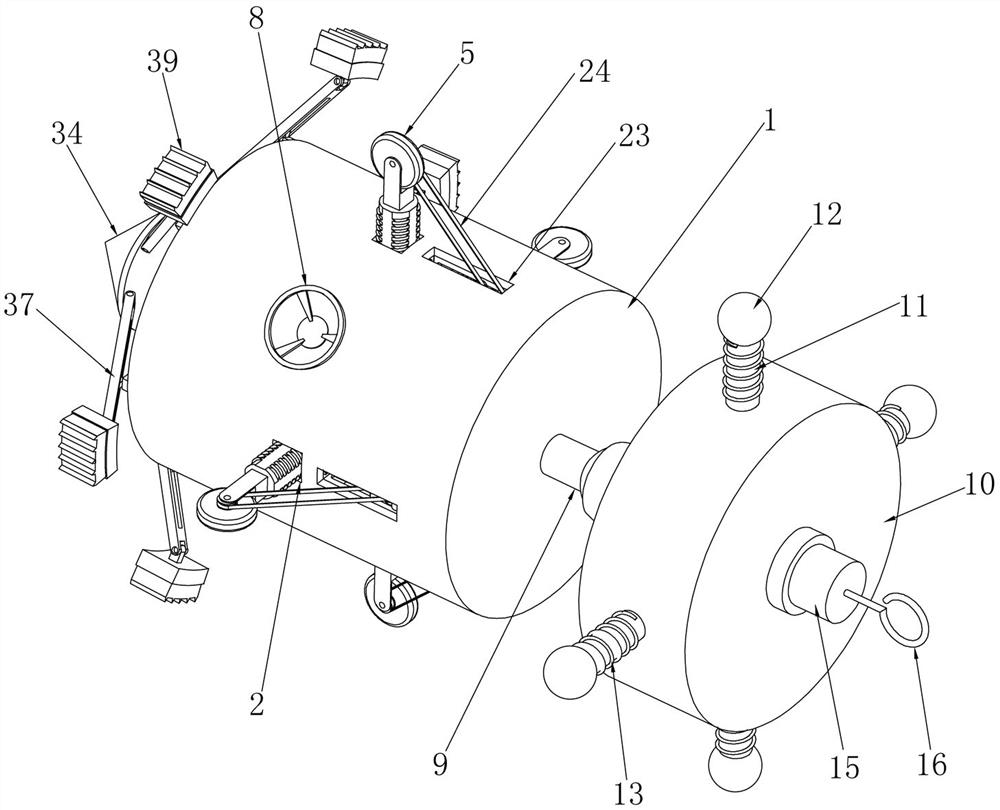
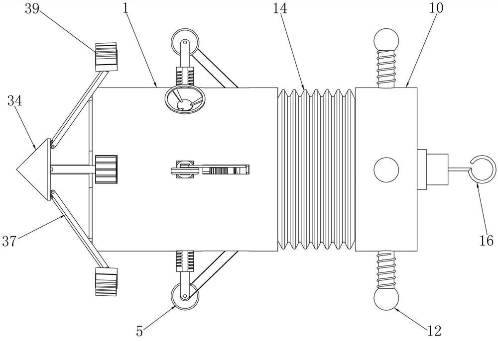
[0034] Embodiment 1, the present invention is a buried pipe pay-off device for water conservancy projects, which includes an outer cylinder 1 with closed left and right ends, and the outer cylinder 1 provides a fixed foundation for the subsequent structure. It is characterized in that the outer cylinder 1 Square adjustment holes 2 are respectively opened on the front, rear, upper and lower sides, and the four adjustment holes 2 respectively pass through the side wall of the outer cylinder 1, and a square adjustment screw rod 3 is slidingly installed in the four adjustment holes 2, respectively. The screw rods 3 can slide radially around in the adjusting cylinder 2 at the same time. When the four adjusting screw rods 3 slide outward, the distance between the four adjusting screw rods 3 becomes larger, that is, the axis of the outer cylinder 1 to the adjusting screw rods 3 The distance from the top of the top is the radius. When the adjusting screw 3 slides, the radius changes ac...
Embodiment 2
[0038] Embodiment 2. On the basis of Embodiment 1, square telescopic holes 17 are respectively opened at the ends of the four adjustment screw rods 3 located outside the outer cylinder 1. The cross-sections of the four walking wheel shafts 4 are square and respectively Slidingly installed in the four telescopic holes 17, the telescopic springs 18 between the walking wheel shaft 4 and the telescopic holes 17 are installed respectively in the four telescopic holes 17, when the positions of the four adjusting screw mandrels 3 are adjusted, the four When a walking wheel 5 drives the outer cylinder 1 to walk in the buried pipe, if there is a protrusion or foreign matter on the inner wall of the pipe, the walking wheel shaft 4 can slide into the telescopic hole 17 and compress the telescopic spring 18. When passing through the protrusion or foreign matter Under the action of the telescopic spring 18, the traveling wheel shaft 4 slides outwards, so that the traveling wheel 5 walks clo...
Embodiment 3
[0039] Embodiment 3, on the basis of Embodiment 1, the tensioning device includes tensioning slide plates 27 fixedly installed on the inner wall of the outer cylinder 1 and respectively flush with the two sides of each transmission groove 23, and each group of Tensioning chute 28 in the left and right direction is respectively opened on the tensioning slide plate 27, and two tensioning wheels 29 are respectively slidably installed in the tensioning chute 28 described in each group, and the shafts of the two tensioning wheels 29 can respectively Slide left and right in the two tensioning chutes 28, the tensioning wheel 29 can rotate on the shaft, and the right end of each group of tensioning slides 27 is respectively fixedly equipped with a spring plate 30 perpendicular to the two tensioning slides 27, so The spring plate 30 runs through and is slidably installed with a tensioning spring bar 31 left and right, the tensioning spring bar 31 can slide left and right on the spring p...
PUM
 Abstract
Description
Claims
Application Information
 - R&D
- Intellectual Property
- Life Sciences
- Materials
- Tech Scout
- Unparalleled Data Quality
- Higher Quality Content
- 60% Fewer Hallucinations
Browse by: Latest US Patents, China's latest patents, Technical Efficacy Thesaurus, Application Domain, Technology Topic, Popular Technical Reports.
© 2025 PatSnap. All rights reserved.Legal|Privacy policy|Modern Slavery Act Transparency Statement|Sitemap|About US| Contact US: help@patsnap.com