
Antenna directional diagram test method and equipment, and storage medium

An antenna pattern and testing method technology, applied in the field of control, can solve the problems affecting the test effect of the antenna pattern, the multi-manpower cost and construction cost, and the high cost of building a microwave anechoic chamber, so as to improve the test effect, reduce the dependence and reduce the research and development. cost effect

Pending Publication Date: 2020-12-18
SZ DJI TECH CO LTD
View PDF7 Cites 3 Cited by
  • Summary
  • Abstract
  • Description
  • Claims
  • Application Information

AI Technical Summary

Problems solved by technology

[0002] The test of the antenna pattern depends on the echo of the test target, and the test target generally uses a stationary corner reflector with a fixed position, because the corner reflector is located at zero Doppler in the frequency domain, and ground clutter is also mainly located at Zero Doppler, so ground clutter will affect the test effect of the antenna pattern
The current common solution is to build a microwave anechoic chamber and use wave-absorbing materials to absorb ground clutter, but the construction cost of the microwave anechoic chamber is extremely high, requires more capital investment, and also requires more labor costs and construction costs, so it cannot meet the requirements. The needs of most researchers

Method used


Image

  • Antenna directional diagram test method and equipment, and storage medium
  • Antenna directional diagram test method and equipment, and storage medium
  • Antenna directional diagram test method and equipment, and storage medium

Examples


Embodiment Construction

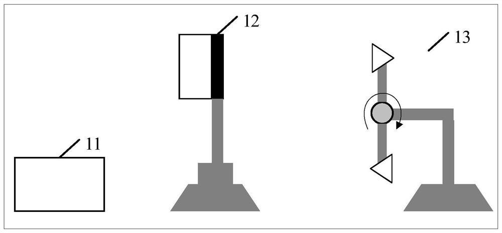
[0025] The technical solutions in the embodiments of the present invention will be clearly described below in conjunction with the accompanying drawings in the embodiments of the present invention. Obviously, the described embodiments are only some, not all, embodiments of the present invention. Based on the embodiments of the present invention, all other embodiments obtained by persons of ordinary skill in the art without making creative efforts belong to the protection scope of the present invention.

[0026] Some embodiments of the present invention will be described in detail below in conjunction with the accompanying drawings. In the case of no conflict, the following embodiments and features in the embodiments can be combined with each other.

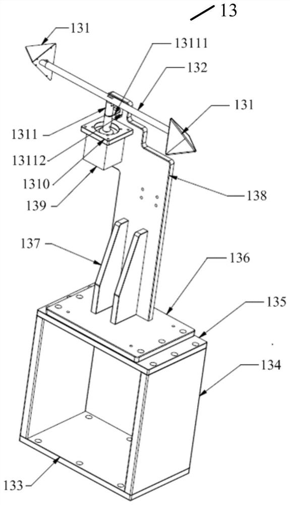
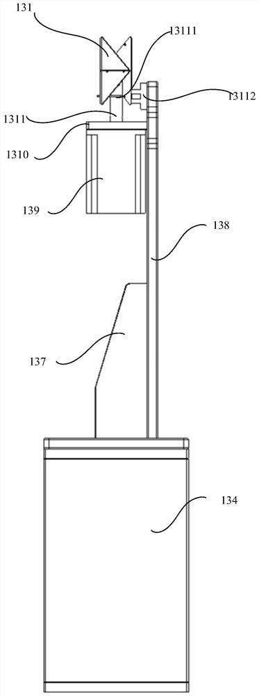
[0027] The antenna pattern testing method provided in the embodiment of the present invention may be executed by an antenna pattern testing system, specifically, may be executed by an antenna pattern testing device in the antenna ...


PUM


Abstract

An antenna directional diagram test method and equipment, an antenna and a storage medium, the method comprising: acquiring echo data generated by the antenna emitting electromagnetic waves to a target scene, the target scene comprising a rotating reflector device (S301); determining target echo data corresponding to the rotating reflector device according to the echo data (S302); and determininga directional diagram of the antenna according to the target echo data (S303). The method can reduce the dependence of the antenna directional diagram on the test environment and the research and development cost, and improve the test effect.

Description

technical field [0001] The present invention relates to the field of control technology, in particular to an antenna pattern test method, equipment and storage medium. Background technique [0002] The test of the antenna pattern depends on the echo of the test target, and the test target generally uses a stationary corner reflector with a fixed position, because the corner reflector is located at zero Doppler in the frequency domain, and ground clutter is also mainly located at Zero Doppler, so ground clutter will affect the test effect of the antenna pattern. The current common solution is to build a microwave anechoic chamber and use wave-absorbing materials to absorb ground clutter, but the construction cost of the microwave anechoic chamber is extremely high, requires more capital investment, and also requires more labor costs and construction costs, so it cannot meet the requirements. The needs of most researchers. [0003] Therefore, how to better test the antenna p...

Claims


Application Information

Patent Timeline
Patent Type & Authority Applications(China)
IPC IPC(8): G01R29/10
CPCG01R29/10
Inventor 汤一君陈雷薛彤晖
Owner SZ DJI TECH CO LTD
Learn More