
Civil air defense door frame hydraulic correcting device

A civil air defense door frame and hydraulic technology, which is applied to the feeding device, positioning device, storage device, etc., can solve the problems of poor welding quality, low positioning accuracy, and large workload of manual welding, saving hoisting time and ensuring correction accuracy. , the effect of preventing bumps

Pending Publication Date: 2020-12-22
广西农业机械研究院有限公司
View PDF0 Cites 0 Cited by
  • Summary
  • Abstract
  • Description
  • Claims
  • Application Information

AI Technical Summary

Problems solved by technology

The production of civil air defense door frames needs to go through multiple steps such as welding, rectification, and painting. At present, most of the production methods of civil air defense door frames in my country still use manual positioning and clamping, manual welding, manual lifting and turnover transportation, etc. Due to the workload of manual positioning and clamping Large size, low positioning accuracy, poor quality of manual welding, and it is not easy to control the amount of welding deformation, which affects the product qualification rate and increases the difficulty of subsequent corrections. Low efficiency and unstable product quality

Method used


Image

  • Civil air defense door frame hydraulic correcting device
  • Civil air defense door frame hydraulic correcting device
  • Civil air defense door frame hydraulic correcting device

Examples


Embodiment Construction

[0021] The present invention will be further described below in conjunction with the accompanying drawings.

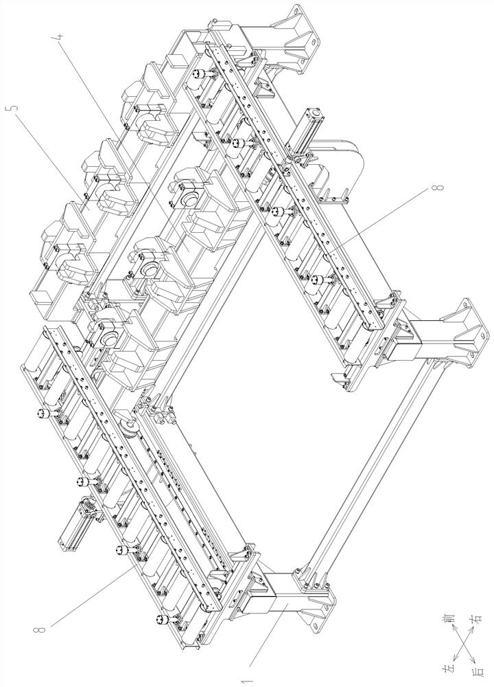
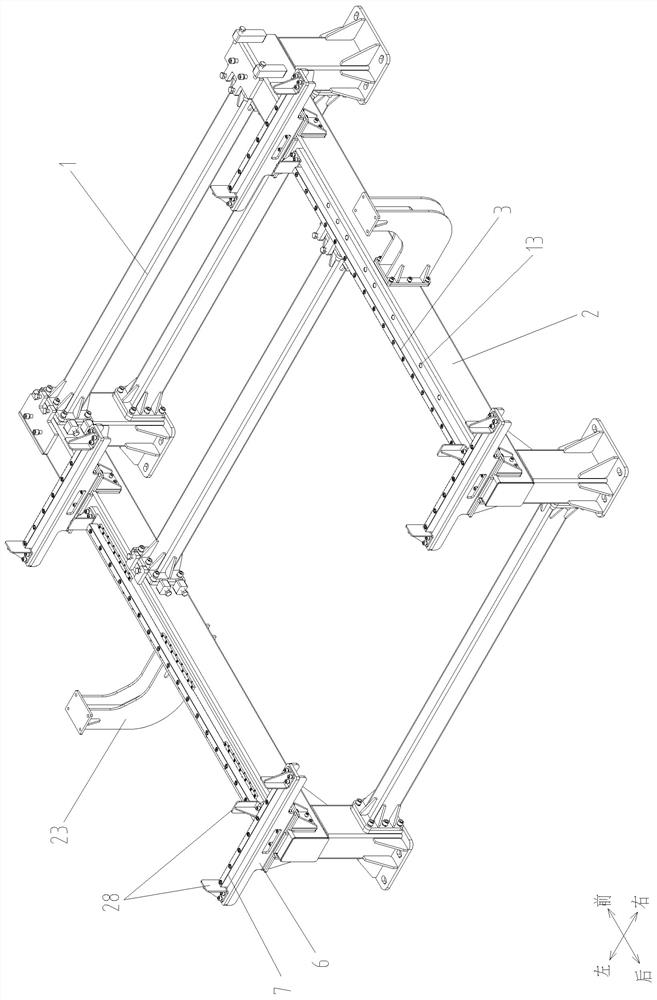
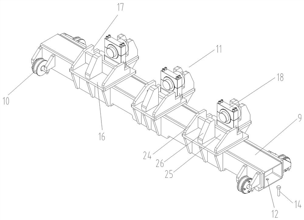
[0022] Such as Figure 1-5 As shown, the personal anti-door frame hydraulic correction device is provided with an underframe 1, a longitudinal beam 2 is respectively provided on the left and right sides of the underframe 1, and a longitudinal guide rail 3 is provided on each fixed frame at the middle and rear of the two longitudinal beams 2 top surfaces. The horizontal span on the two longitudinal guide rails 3 has a movable beam correction assembly 4 that can slide back and forth along the longitudinal guide rails 3, and the front transverse span on the top surface of the two longitudinal beams 2 has a fixed beam correction assembly 5; the two longitudinal beams 2 The top surface is respectively erected with a section of horizontal guide rail 7 which is set up through the guide rail seat 6 at the front and rear ends of the longitudinal guide rail 3, and there is a lon...


PUM


Abstract

The invention provides a civil air defense door frame hydraulic correcting device. Longitudinal beams are arranged the left side and the right side of a bottom frame of the civil air defense door frame hydraulic correcting device correspondingly. Longitudinal guide rails are fixedly erected on the middle rear portions of the top faces of the longitudinal beams correspondingly. A movable beam correcting assembly capable of sliding forwards and backwards along the longitudinal guide rails is transversely erected on the left longitudinal guide rail and the right longitudinal guide rail in a spanning manner. A fixed beam correcting assembly is transversely erected on the front portions of the top surfaces of the two longitudinal beams in a spanning manner. Transverse guide rails erected through guide rail bases are erected on the portions, at the front ends and the rear ends of the longitudinal guide rails, of the top faces of the two longitudinal beams correspondingly. Conveying roller assemblies capable of sliding leftwards and rightwards along the transverse guide rails are erected on the portions, on the front portions and the rear portions, of the transverse guide rails on the left side and the right side correspondingly. The hydraulic correcting device can be suitable for civil defense door frames with the same height and different width specifications as long as the positions, on the longitudinal guide rails, of the movable beam correcting assembly are changed and locked. After correction of the civil air defense door frames is completed, the civil air defense door frames can be conveyed backwards to a subsequent station through the conveying roller assemblies on the left side and the right side, and therefore rapid circulation is achieved, and time is saved.

Description

technical field [0001] The invention relates to a civil air defense door frame manufacturing equipment, in particular to a hydraulic correction device for a civil air defense door frame, which belongs to the technical field of mechanical correction equipment. Background technique [0002] Civil air defense doors are important access protection equipment in civil air defense engineering facilities, and civil air defense doors need to be equipped with civil air defense door frames for installation. The civil air defense door frame is generally welded by four angle steels, four pressure bearing plates, four embedded pressure edges and two hinge bases, among which the four angle steels are respectively used as long-side angle steel and wide-side angle steel to form a rectangular door frame. Four pressure bearing plates and four embedding edges are welded on the outer frame surface of the rectangular door frame and form a closed loop, and two hinge bases are welded on the outer e...

Claims


Application Information

Patent Timeline
Patent Type & Authority Applications(China)
IPC IPC(8): B21D3/16B21D43/08
CPCB21D3/16B21D43/08
Inventor 周楚虹黎向新罗健梁挺新李之路陆济海吴锡赞缪利峰
Owner 广西农业机械研究院有限公司
Learn More