
Illumination system with detection function

A lighting system and functional technology, applied in the field of lighting systems with detection functions, can solve problems such as difficult to achieve accurate detection of lighting areas, increase cost system redundancy, etc., to achieve the effects of improving safety, achieving accurate matching, and reducing costs

Pending Publication Date: 2020-12-22
SHENZHEN LASER INST
View PDF5 Cites 0 Cited by
  • Summary
  • Abstract
  • Description
  • Claims
  • Application Information

AI Technical Summary

Problems solved by technology

However, adding an additional independent detection system will increase the cost and overall system redundancy. Moreover, if the detection system and the lighting system are independent of each other, it is difficult to achieve accurate detection of the lighting area where the lights are dynamically turned off.

Method used


Image

  • Illumination system with detection function
  • Illumination system with detection function
  • Illumination system with detection function

Examples


Embodiment Construction

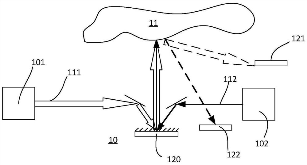
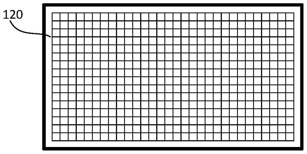
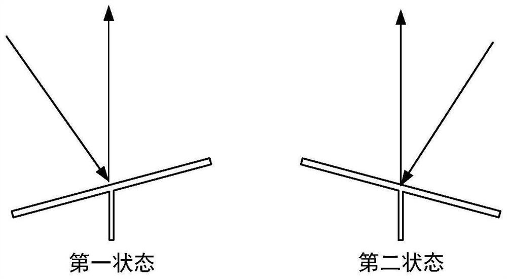
[0027]The embodiments of the present invention will be described in detail below with reference to the accompanying drawings and embodiments. Seefigure 1 , Is a schematic structural diagram of the lighting system according to the first embodiment of the present invention.

[0028]The illumination system 10 includes an illumination light source 101, a first detection light source 102, a light modulation device 120, a first sensor 121 and a second sensor 122.

[0029]The illuminating light source 101 emits illuminating light 111, and the illuminating light 111 exits through the light modulating device 120 through the illuminating light path. The light modulating device 120 modulates the spatial distribution of the illuminating light 111 to obtain a refined lighting distribution of brightness and darkness. Then, the light reflected by the target object 11 returns to the illumination system 10 and is received by the first sensor 121. The illumination light source 101 may include a semiconduct...


PUM


Abstract

The invention provides an illumination system with a detection function. The illumination system comprises an illumination light source, a first detection light source and a light modulation device, wherein the illumination light source is used for emitting illumination light, and the illumination light is emitted through an illumination light path; the first detection light source is used for emitting first detection light, and the first detection light is emitted through a first detection light path; and the light modulation device is arranged on the illumination light path and the first detection light path and used for modulating spatial distribution of the illumination light and the first detection light, so that the illumination light and the first detection light are emitted simultaneously in at least part of time period, and a complementary pattern is formed on the emitting side of the light modulation device. According to the technical scheme, detection monitoring is carried out on a non-illumination area, accurate matching of the illumination and detection complementary pattern is achieved through modulation of the same light modulation device, the safety is improved, andmeanwhile the overall cost is reduced.

Description

Technical field[0001]The present invention relates to the field of lighting technology, in particular to a lighting system with a detection function.Background technique[0002]Automotive headlight sources have undergone upgrades from halogen lamps, xenon lamps to LED headlights. At present, LED automotive headlights have begun to spread in the automotive market. Compared with other light sources, laser light sources have high brightness, high energy efficiency, long life, small size, good directionality and fast start-up speed, etc., making laser headlights a new development trend after LED headlights, and has begun to be used in Part of the high-end car market.[0003]Due to the small divergence angle of the laser and easy control of the direction, companies such as Texas Instruments and Audi have successively proposed laser headlight concept products based on digital micromirror arrays (such as DMD, Digital Micromirro Device), which can be controlled by an intelligent controller. Col...

Claims


Application Information

Patent Timeline
IPC IPC(8): F21S41/675F21S41/64G01S17/42G01S17/88B60Q1/06F21W107/10
CPCF21S41/675F21S41/645G01S17/42G01S17/88B60Q1/06F21W2107/10F21S41/64F21S43/00F21V14/04F21S41/30F21S41/36F21S41/00
Inventor 王雷巫英坚
Owner SHENZHEN LASER INST
Learn More