
Dangerous area detection method and system based on active and passive seismic source signals, terminal and readable storage medium

An active source, dangerous area technology, applied in seismic signal processing, seismology, measurement devices, etc., can solve problems such as difficulty in ensuring inversion accuracy, lack of accurate positioning methods for passive sources, and limiting the application of wave velocity imaging technology. Technical barriers, the effect of improving reliability

Active Publication Date: 2020-12-22
CENT SOUTH UNIV
View PDF17 Cites 7 Cited by
  • Summary
  • Abstract
  • Description
  • Claims
  • Application Information

AI Technical Summary

Problems solved by technology

According to different types of seismic sources, the wave velocity field imaging technology can be divided into active source wave velocity imaging technology and passive source wave velocity imaging technology. Although the use of active source ensures the accuracy of the source position, all production must be stopped during the release of the active source. activities, which greatly limit the application of wave velocity imaging technology in the field. On the other hand, although passive seismic sources such as blasting operations and mechanical rock drilling can ensure the continuous release of signals, there is a lack of accurate positioning of passive seismic sources under complex rock structures. , it is difficult to guarantee the accuracy of the inversion

Method used


Image

  • Dangerous area detection method and system based on active and passive seismic source signals, terminal and readable storage medium
  • Dangerous area detection method and system based on active and passive seismic source signals, terminal and readable storage medium
  • Dangerous area detection method and system based on active and passive seismic source signals, terminal and readable storage medium

Examples


Embodiment Construction

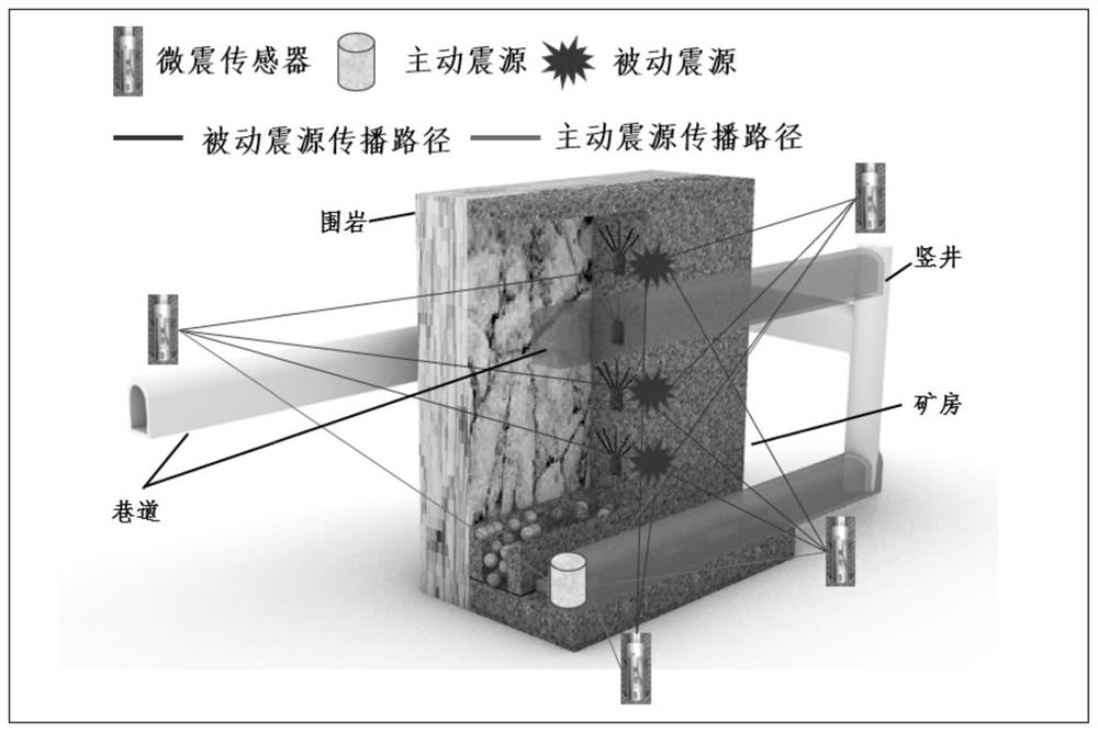
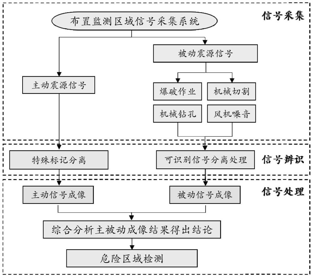
[0048] A dangerous area detection method based on active and passive seismic source signals provided by the present invention is a means of detecting gobs by combining active seismic sources and passive seismic sources. Among them, the active seismic source is placed at the center of the monitoring area, and the impact on the measuring point is released at regular intervals to release microseismic waves; secondly, since the active seismic source is released with operations such as mining and excavation, it is necessary to monitor the active seismic source signal and passive (engineering) Disturbance) signals are identified; then the source of the passive source signal is positioned and the seismic wave velocity imaging is performed on the active source signal and the passive source signal respectively; finally, the wave velocity imaging results of the two types of source signals are comprehensively analyzed to evaluate the stability of the rock mass in the monitoring area and de...


PUM


Abstract

The invention discloses a dangerous area detection method and system based on active and passive seismic source signals, a terminal and a readable storage medium. The method comprises the following steps: step 1, acquiring seismic source signals, and arranging a micro-seismic sensor and an active seismic source in a monitoring area; step 2, identifying each seismic source signal as an active seismic source signal or a passive seismic source signal; step 3, positioning the passive seismic source signal to obtain a passive seismic source position and a passive seismic source signal release moment; step 4, inverting a monitoring area wave velocity field of the active seismic source signal and a monitoring area wave velocity field of the passive seismic source signal; and step 5, comparing themonitoring area wave velocity field of the active seismic source signal with the monitoring area wave velocity field of the passive seismic source signal to judge a goaf. According to the method, theactive seismic source and the passive seismic source are combined for positioning, and the goaf judgment precision is improved.

Description

technical field [0001] The invention belongs to the technical field of microseismic monitoring and early warning, and in particular relates to a dangerous area detection method based on active and passive seismic source signals. Background technique [0002] With the reduction and depletion of shallow resources year by year, the mining of mineral resources at home and abroad is developing to the deep. The rock mass under high stress is affected by engineering disturbances such as mechanical rock drilling and blasting operations, resulting in stress concentration in the surrounding rock mass. Stress redistribution phenomena such as stress release and stress release make the originally stable rock mass into an unstable state, which greatly threatens the safety of construction personnel and equipment. Engineering disturbance will deform the rock mass and even promote the expansion of cracks inside the rock mass. During this process, the elastic potential energy stored inside th...

Claims


Application Information

Patent Timeline
IPC IPC(8): G01V1/28G01V1/30G06K9/00G06N3/04
CPCG01V1/288G01V1/307G01V2210/65G06N3/045G06F2218/08
Inventor 董陇军唐正
Owner CENT SOUTH UNIV
Learn More