
Movable solar panel fixing and mounting mechanism

A technology of solar panel and installation structure, which is applied to mobile/orientation solar collectors, fixed bases/supports of solar collectors, solar thermal energy, etc. It can solve problems such as complex installation mechanisms, meet lighting requirements and facilitate adjustments , Easy to disassemble and move

Active Publication Date: 2020-12-22
HEFEI LISTEN NEW ENERGY TECH
View PDF4 Cites 0 Cited by
  • Summary
  • Abstract
  • Description
  • Claims
  • Application Information

AI Technical Summary

Problems solved by technology

[0003] The purpose of the present invention is to provide a movable solar panel fixing and installation mechanism. The fixed part provided is an L-shaped structure, which is convenient to be clamped on the right-angle frame of the solar panel, and the extended plate of the clamping part after the flip It is connected to the upper side of the solar panel, which is convenient for fixing. The bolts passing through the fixing hole and the limit hole in turn are fixed and installed. The existing solar panel installation mechanism is complicated

Method used


Image

  • Movable solar panel fixing and mounting mechanism
  • Movable solar panel fixing and mounting mechanism
  • Movable solar panel fixing and mounting mechanism

Examples


Embodiment Construction

[0033] The following will clearly and completely describe the technical solutions in the embodiments of the present invention with reference to the accompanying drawings in the embodiments of the present invention. Obviously, the described embodiments are only some, not all, embodiments of the present invention. Based on the embodiments of the present invention, all other embodiments obtained by persons of ordinary skill in the art without creative efforts fall within the protection scope of the present invention.

[0034] In describing the present invention, it is to be understood that the terms "opening", "upper", "lower", "thickness", "top", "middle", "length", "inner", "surrounding" etc. Indicating orientation or positional relationship is only for the convenience of describing the present invention and simplifying the description, and does not indicate or imply that the components or elements referred to must have a specific orientation, be constructed and operated in a sp...


PUM


Abstract

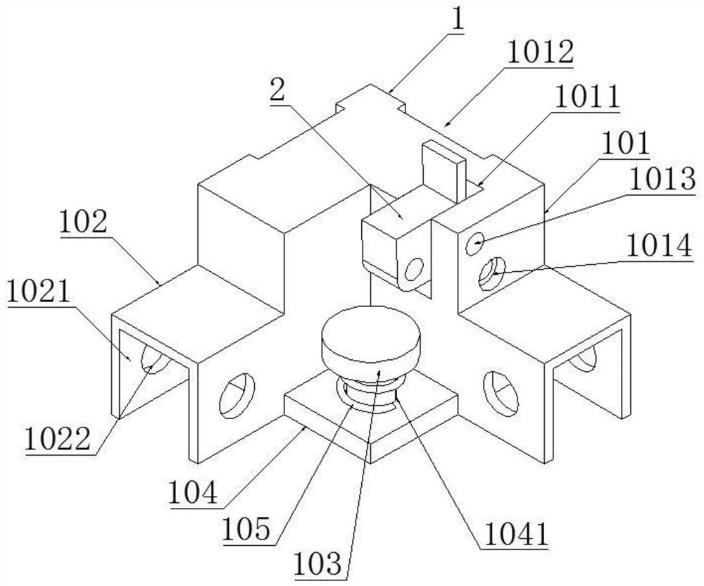
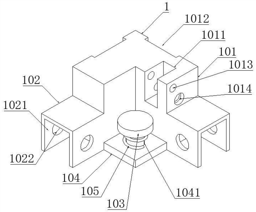
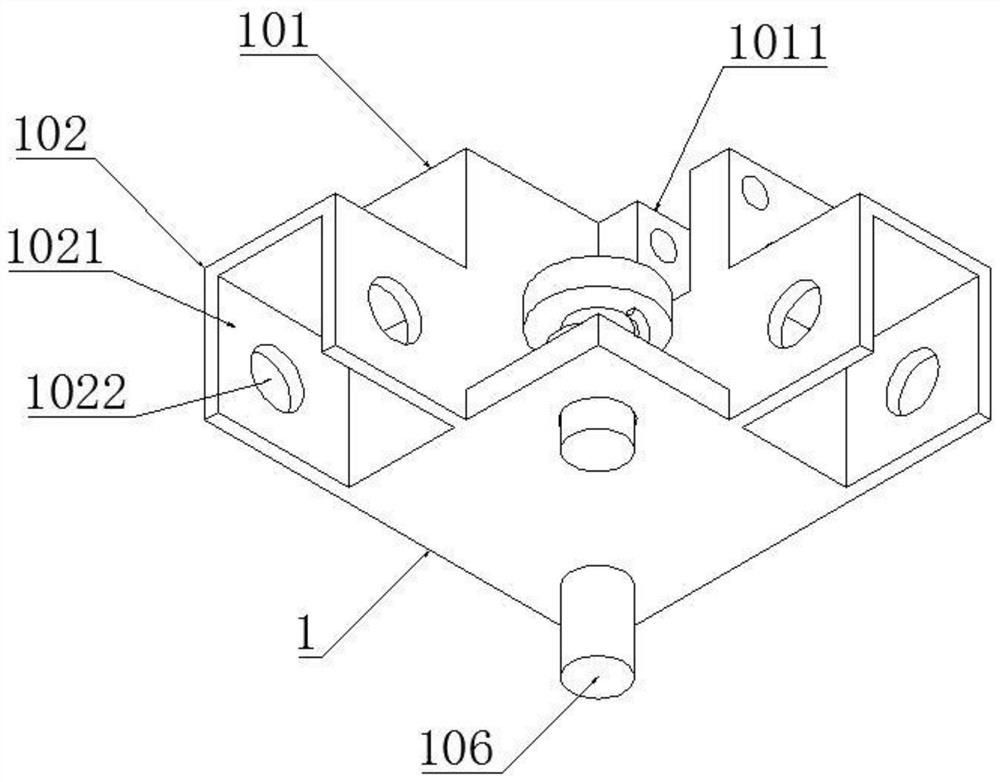
The invention discloses a movable solar panel fixing and mounting mechanism, and relates to the technical field of fixing mechanisms. The fixing device comprises a fixed part and a clamping part, wherein the fixed part comprises a convex block and a base; wherein the base is of an L-shaped structure, and mounting structures are arranged at the two end parts of the base; a protruding block is arranged on the L-shaped side face of the base, a mounting base is arranged on one inner side face of the protruding block, and a first pin hole and a through hole are formed in the two opposite side facesof the mounting base respectively. A second pin hole corresponding to the first pin hole and a limiting hole corresponding to the through hole are formed in the clamping part in a penetrating manner,the clamping part is rotatably mounted in the mounting seat by penetrating through the pin first hole and the second pin hole, an arranged screw rod can sequentially penetrate through the through hole and the limiting hole, and at the moment, an extension plate arranged on one side surface of the clamping part is kept horizontal. The fixed part is of an L-shaped structure and can be convenientlyclamped to a right-angle frame body of the solar cell panel, the extension plate of the overturned clamping part is connected to the upper side face of the solar cell panel in an overlapped mode, thereby facilitating the fixing.

Description

technical field [0001] The invention belongs to the technical field, and in particular relates to a movable solar panel fixed installation mechanism. Background technique [0002] Due to the large consumption of traditional energy such as oil and its limited storage capacity, and its serious pollution to the environment, people pay more and more attention to clean energy such as wind energy and solar energy. In particular, solar energy has less geographical restrictions and is rich in energy. , has increasingly become a research focus and focus. The development of clean energy has promoted the development of a new round of energy economy, and photovoltaic power generation technology has become the main force in the development of new energy. The installation mechanism of the existing solar panel is complicated and inconvenient to move. Contents of the invention [0003] The purpose of the present invention is to provide a movable solar panel fixing and installation mecha...

Claims


Application Information

Patent Timeline
Patent Type & Authority Applications(China)
IPC IPC(8): H02S30/10H02S20/30F24S25/13F24S25/20F24S25/63F24S30/00
CPCH02S30/10H02S20/30F24S25/13F24S25/20F24S25/63F24S30/00Y02E10/47Y02E10/50
Inventor 陈生明范德玉张浩苏电鹏
Owner HEFEI LISTEN NEW ENERGY TECH
Learn More