Foldable toilet apparatus for helping aged

A foldable and foldable rack technology, applied in transportation and packaging, vehicle rescue, medical transportation, etc., can solve the problems of hard corners, injuries, and difficult to use, and achieves the effect of less floor space and simple operation.

Inactive Publication Date: 2020-12-25
TIANJIN UNIV OF TECH & EDUCATION TEACHER DEV CENT OF CHINA VOCATIONAL TRAINING & GUIDANCE
13 Cites 1 Cited by

AI-Extracted Technical Summary

Problems solved by technology

[0002] With the rise of the 5G era, intelligent and convenient wheelchairs are a necessary tool for the elderly to go to the toilet conveniently. Because the ...

Method used

Specific embodiment one: as shown in Fig. 1~Fig. 12, the present invention discloses a kind of collapsible device for helping the elderly to go to the toilet, including slide rail 27, support base plate 15, pedal 62, handrail 5, backrest 41. Seat plate 61, backrest driving system mechanism 2010, mechanical pressure-sensitive mechanism 2011, folding mechanism and traveling wheels; the lower end of the support base plate 15 is provided with traveling wheels (the traveling wheels are two universal wheels 9 and two Drive wheel 12, a drive wheel motor 33 is respectively fixed on the left and right sides of the front end of the support base plate 15, each of the drive wheel motors 33 drives the corresponding drive wheel 12 respectively, and a ten thous...

Abstract

The invention discloses foldable toilet apparatus for helping the aged, and relates to equipment for helping the aged. According to the foldable toilet apparatus, walking wheels are arranged at the lower end of a supporting bottom plate, a foot pedal is fixedly arranged at the front end of the supporting bottom plate, the upper end of the supporting bottom plate is in folding connection with sliding rails through a folding mechanism, the sliding rails are connected with a seat plate through a mechanical pressure sensing mechanism, the seat plate is connected with a backrest through a backrestdriving system structure, and the backrest and the seat plate are connected with armrests. According to the foldable toilet apparatus, two normal states of helping the aged to stand up and helping theaged to sit down can be realized, the labor is saved, the safety is achieved, the operation is simple, the automatic folding and storage can be achieved when the apparatus is not used by the aged, and an occupied space is small.

Application Domain

Wheelchairs/patient conveyance

Technology Topic

Mechanical pressureMechanical engineering +5

Image

  • Foldable toilet apparatus for helping aged
  • Foldable toilet apparatus for helping aged
  • Foldable toilet apparatus for helping aged

Examples

  • Experimental program(4)

Example Embodiment

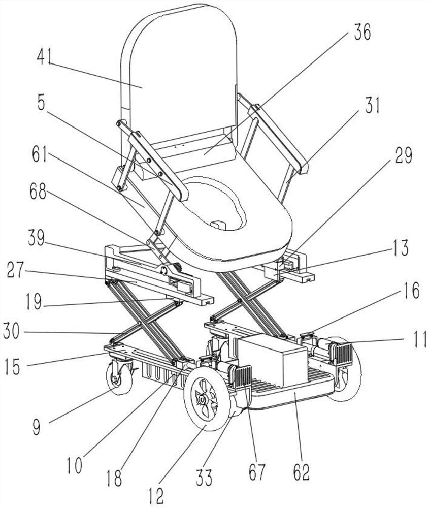
[0027] Specific implementation mode one: as Figure 1 to Figure 12 As shown, the present invention discloses a foldable toilet device for the elderly, which includes a slide rail 27, a support base plate 15, a pedal 62, an armrest 5, a backrest 41, a seat plate 61, a backrest driving system mechanism 2010, a mechanical press Sensing mechanism 2011, folding mechanism and walking wheel; The lower end of described supporting base plate 15 is provided with traveling wheel (the described walking wheel is two universal wheels 9 and two driving wheels 12, and the left and right sides of supporting base plate 15 front ends are fixed respectively There is a driving wheel motor 33, each of the driving wheel motors 33 drives the corresponding driving wheel 12 respectively, a universal wheel 9) is respectively fixed on the left and right sides of the support base plate 15 rear end, and the front end of the support base plate 15 is fixed with a pedal Plate 62, the pedal 62 is preferably made of rubber material to improve the anti-skid performance; the upper end of the support base plate 15 is folded and connected with the slide rail 27 through a folding mechanism, and the slide rail 27 is connected to the seat plate 61 through a mechanical pressure-sensitive mechanism 2011 The seat board 61 is connected with the backrest 41 through the backrest driving system mechanism 2010 , and the backrest 41 and the seat board 61 are connected with the armrest 5 through the parallelogram connecting rod 31 .

Example Embodiment

[0028] Specific implementation mode two: as figure 1 As shown, this embodiment is a further description of Embodiment 1. The folding mechanism includes two folding parts arranged side by side at the left and right ends of the support base 15, and each of the folding parts includes a travel limit switch 10, Linear motor 11, connecting plate 13, spine structure shell 29 and X-type folding frame 30; Described linear motor 11 is horizontally fixed on the front end of support base plate 15, and the outer end of linear motor 11 is provided with protective plate 67, and linear motor 11 The upper end is provided with a limit support mechanism 16, and the movable end of the linear motor 11 is set in cooperation with the stroke limit switch 10 through the linear motor connector 18, and the linear motor connector 18 is provided with a stroke limit switch 10 when it reaches the predetermined stroke position during the movement. The linear motor 11 is connected with one end of the lower end of the X-type folding frame 30 arranged vertically, the other end of the lower end of the X-type folding frame 30 is connected with the support base plate 15 by the X-type folding frame hinge 64, and one end of the X-type folding frame 30 upper end It is slidingly connected with the slide rail 27 through the slider 19, and the slider 19 is fixedly connected with the ratchet structure shell 29 through the connecting plate 13, and the other end of the upper end of the X-shaped folding frame 30 is connected with the slide rail 27 through the X-shaped folding frame hinge 64 .

Example Embodiment

[0029] Specific implementation mode three: as image 3 , 4 , 5, and 6, this embodiment is a further description of the second specific embodiment. The backrest drive system mechanism 2010 includes an intermediate support 39, a gear 211, a rack 219, an upper ratchet bar 236, a lower ratchet bar 256, Hinge four-bar mechanism 68, fixed guide 204, support frame 238, return pin 240, lower spine 256 and rotating shaft 291; The inside of described spine structure shell 29 is fixedly connected with support frame 238 by set screw 258, so The support frame 238 is provided with a horizontally arranged lower ratchet bar 256 that can move up and down (the positioning holes at the lower end of the support frame 238 are equipped with a plurality of fixed mandrels 201, and the outer sides of the plurality of fixed mandrels 201 are The spring 206 is sleeved and the upper end is fixedly connected with the lower ratchet bar 256, and the two ends of each spring 206 respectively lean against the lower ratchet bar 256 and the support frame 238, so that the lower ratchet bar 256 can move up and down in the support frame 238) , the lower spine 256 is meshed with the upper spine 236, and connected through the fixed guide 204, the upper spine 236 is connected with the support frame 238 through a sliding groove, and the upper spine 236 is connected by a plurality of hexagon socket screws 257 is fixedly connected with the rack 219, and the rack 219 is meshed with the vertically arranged gear 211. The gear 211 is fixedly set on the outside of one end of the rotating shaft 291 through the key 179, and the end surface is fixedly connected with the hinge four-bar mechanism 68. The other end of the rotating shaft 291 is rotationally connected with the intermediate support 39 through a bearing one 292, and the outer side of the bearing one 292 is compressed by a bearing stop ring 290, and a bearing through cover 294 is also provided; the intermediate support 39 is fixed on the slide The upper end of the rail 27 and the outside of the support frame 238 are elastically connected to the return pin 240 through the return spring 244. The return pin 240 is connected to the upper ratchet bar 236, and a sleeve 293 is also provided between the rotating shaft 291 and the gear 211. The sleeve 293 is compressed by the shaft end retaining ring 175 and the screw 176 .

PUM

no PUM

Description & Claims & Application Information

We can also present the details of the Description, Claims and Application information to help users get a comprehensive understanding of the technical details of the patent, such as background art, summary of invention, brief description of drawings, description of embodiments, and other original content. On the other hand, users can also determine the specific scope of protection of the technology through the list of claims; as well as understand the changes in the life cycle of the technology with the presentation of the patent timeline. Login to view more.

Similar technology patents

Household appliance control method and device and mobile terminal

InactiveCN103605531Aeasy to operateeasy to use
Owner:GD MIDEA AIR-CONDITIONING EQUIP CO LTD +1

Graphene film and preparation method therefor

Owner:CHANGZHOU FUXI TECH CO LTD

Driving working load calculation method of automobile driver

InactiveCN101690666AImprove accuracy and timelinessEasy to operate
Owner:BEIJING UNIV OF TECH

Laser radar optical system with optical axis calibrating function and optical axis calibrating method

InactiveCN102353950AOptical axis alignment with high precisioneasy to operate
Owner:INST OF APPLIED ELECTRONICS CHINA ACAD OF ENG PHYSICS +1

Classification and recommendation of technical efficacy words

  • easy to operate
  • small footprint

Lancet device

InactiveUS7303573B2inexpensively mass-producedeasy to operate
Owner:ABBOTT DIABETES CARE INC

Rapid and non-invasive optical detection of internal bleeding

InactiveUS20050065436A1easy to operaterapid and accurate result
Owner:HO WINSTON ZONH +2
Why Eureka
Try Eureka