Sauce target manufacturing device

A technology for manufacturing devices and sauce targets, which is applied in the field of manufacturing devices, can solve the problems of low manufacturing qualification rate, cumbersome operation procedures, low work efficiency and the like, and achieves the effects of high qualification rate, simple operation procedures and high work efficiency.

Inactive Publication Date: 2020-12-25
杨华南
View PDF6 Cites 2 Cited by
  • Summary
  • Abstract
  • Description
  • Claims
  • Application Information

AI Technical Summary

Problems solved by technology

[0004] In order to overcome the disadvantages of cumbersome operation procedures, low work efficiency, need to manually tap the long handle and sauce target, and low manufacturing qualification rate, the technical problem of the present invention is to provide a simple operation procedure, high work efficiency, and no need for manual tapping. Sauce target manufacturing device with long handle and sauce target and high pass rate

Method used


Image

  • Sauce target manufacturing device
  • Sauce target manufacturing device
  • Sauce target manufacturing device

Examples


Embodiment 1

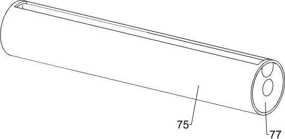
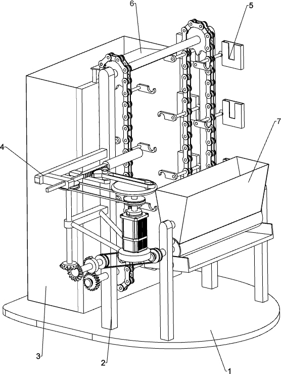
[0042] A sauce target manufacturing device, such as figure 1 As shown, it includes a base 1, a first bracket 2, a collection frame 3, a pressing mechanism 4, a feeding mechanism 5, a baffle plate 6 and a blanking mechanism 7, and the first bracket 2 is arranged in the middle of the top of the base 1, front and rear. A discharge mechanism 5 is connected between the first supports 2, and a compression mechanism 4 is connected between the parts in the discharge mechanism 5 and the top of the first support 2 on the front side. The left side of the top of the base 1 is provided with a collection frame 3, and the collection frame 3. A baffle plate 6 is provided on the right side of the top, and a blanking mechanism 7 is connected between the right side of the top of the base 1 and the components in the discharging mechanism 5.

[0043] When the sauce target needs to be installed, the staff first places a plurality of long handles in the parts in the unloading mechanism 7, then place...

Embodiment 2

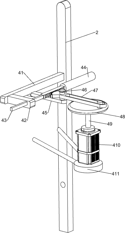
[0045] On the basis of Example 1, such as figure 2 As shown, the pressing mechanism 4 includes a mounting bracket 41, a first sliding sleeve 42, a rack 43, an extruding rod 44, a first connecting rod 45, a fixed column 46, a gear rod 47, a disc 48, and a first rotating shaft 49 , the motor 410 and the mounting base 411, the front side of the first bracket 2 top front side is provided with a mounting frame 41, the right side of the mounting frame 41 front is provided with a first sliding sleeve 42, the first sliding sleeve 42 is slidably connected with a rack 43, the rear end of the rack 43 is provided with an extrusion rod 44, the bottom of the mounting frame 41 is provided with a first connecting rod 45, the first connecting rod 45 is located below the rack 43, and the top right side of the first connecting rod 45 is provided with a fixed column 46. ​​The right side of the discharging mechanism 5 is provided with a mounting seat 411, and the top of the mounting seat 411 is p...

Embodiment 3

[0048] On the basis of Example 2, such as image 3 As shown, the discharge mechanism 5 includes a first transmission assembly 51, a second rotating shaft 52, a first bevel gear 53, a second bevel gear 54, a rotating column 55, a half gear 56, a spur gear 57, a second sliding sleeve 58, The second connecting rod 59, the chain 510, the hook 511 and the plank frame 512, the lower front side of the first support 2 on the front side is provided with a second sliding sleeve 58, and the front portion of the second sliding sleeve 58 is slidably connected with the second rotating shaft 52, The first transmission assembly 51 is rotatably connected between the top of the second rotating shaft 52 and the middle part of the first rotating shaft 49 , the bottom of the second rotating shaft 52 is provided with a first bevel gear 53 , and the lower part of the front side of the first bracket 2 is rotatably connected with Rotation column 55, the rotation column 55 is located below the second s...


PUM


Abstract

The invention relates to a manufacturing device, in particular to a sauce target manufacturing device. The sauce target manufacturing device is simple in operation procedure, high in working efficiency and high in percent of pass, and a long handle and a sauce target do not need to be knocked manually. The sauce target manufacturing device comprises a base, first supports being arranged on the twosides of the top of the base; a discharging mechanism which is rotationally connected between the first supports on the two sides, a pressing mechanism being connected between the discharging mechanism and the first support on the front side; a collecting frame which is arranged on the top of the base close to one side of the first support, a baffle being arranged on one side of the top of the collecting frame; and a discharging mechanism which is connected between the top of the base and the discharging mechanism. Through the mutual cooperation of an installation frame, a first sliding sleeve, a rack and other components, an extrusion rod knocks a long handle, the long handle is knocked into a wood plate, and therefore installation of one sauce target is completed, repeated operation isconducted, one-by-one installation of sauce targets is achieved, time and labor are saved, and the working efficiency is high.

Description

technical field [0001] The invention relates to a manufacturing device, in particular to a sauce target manufacturing device. Background technique [0002] At present, from the point of view of the sauce mixing method, one of the important procedures is to install the sauce target used for stirring. Usually, the staff puts the wooden board on the ground, and then aligns the long handle with the wooden board with one hand. And hold the long handle firmly, hold the mallet with the other hand and hit the long handle hard, and knock the long handle into the wooden board, so as to complete the installation of the sauce target one by one, and repeat this operation, so as to realize the installation of the sauce targets one by one, such an operation process It is cumbersome, the work efficiency is relatively low, and manual operation is relatively easy to produce errors, resulting in a low pass rate of sauce targets. [0003] Based on the above-mentioned problems in the manufactur...

Claims


Application Information

Patent Timeline
Patent Type & Authority Applications(China)
IPC IPC(8): B01F15/00
CPCB01F35/40
Inventor 杨华南
Owner 杨华南
Why Eureka
Try Eureka