
Cutting workbench

A technology for working tables and cutting parts, which is applied in the direction of manufacturing tools, metal processing equipment, metal processing machinery parts, etc., and can solve problems such as time-consuming and laborious, cumbersome procedures, and incomplete removal of smoke and dust.

Pending Publication Date: 2020-12-25
上海气焊机厂有限公司
View PDF0 Cites 2 Cited by
  • Summary
  • Abstract
  • Description
  • Claims
  • Application Information

AI Technical Summary

Problems solved by technology

However, the current workbench does not completely remove the smoke and dust generated during cutting, and when discharging the slag from the hopper, it is necessary to stop the cutting machine first, and then use the lifting device to lift the material rack and the hopper respectively. To lift the hopper out of the workbench and dump the slag, this method of slag removal is not only cumbersome but also time-consuming and labor-intensive, and the work efficiency is low

Method used


Image

  • Cutting workbench
  • Cutting workbench
  • Cutting workbench

Examples


Embodiment Construction

[0049] The present invention will be further described in detail below in conjunction with the accompanying drawings and embodiments. It should be understood that the specific embodiments described here are only used to explain the present invention, but not to limit the present invention. In addition, it should be noted that, for the convenience of description, only some structures related to the present invention are shown in the drawings but not all structures.

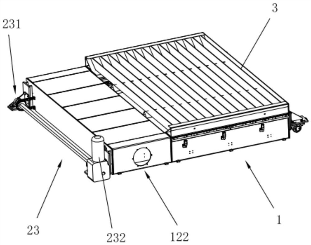
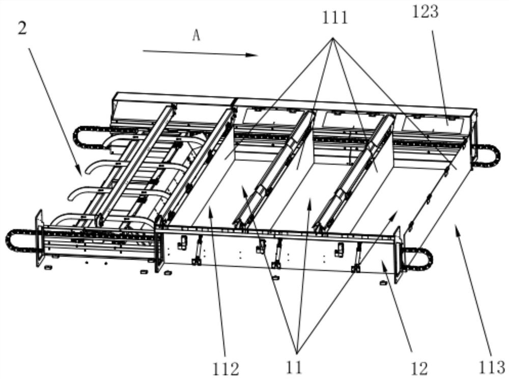
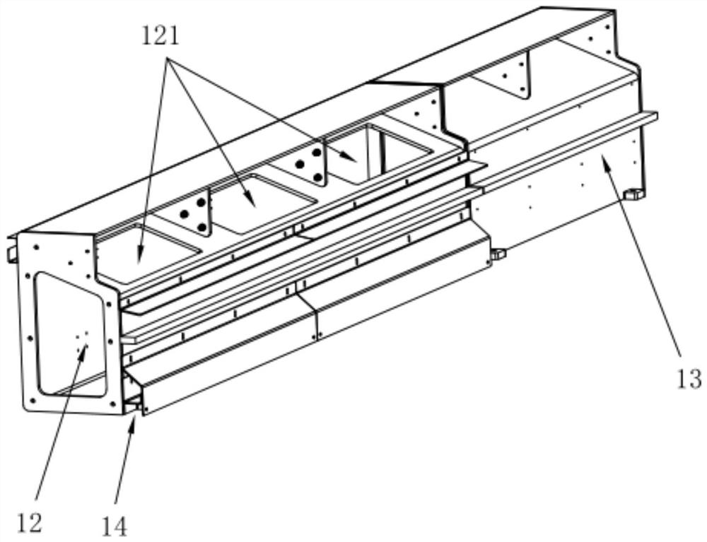
[0050] This embodiment provides a cutting workbench, which is suitable for gantry plasma cutting machines, flame cutting machines, laser cutting machines, etc., and is used to support pieces to be cut and collect waste residues generated during cutting. Such as Figure 1-Figure 3 As shown, the cutting workbench includes a workbench main body 1 and a slag removal device 2. The workbench main body 1 can support the piece to be cut for cutting. The workbench main body 1 is provided with a slag storage chamber 11 for ...


PUM


Abstract

The invention belongs to the technical field of machining equipment, and discloses a cutting workbench which comprises a workbench main body and a slag removal device. A part to be cut is supported through the workbench main body, and a slag storage chamber used for collecting waste slag generated by cutting the part to be cut is arranged in the workbench main body; a dust removal duct is arrangedon the side wall of the slag storage chamber; The interior of the slag storage chamber is divided into a plurality of chambers in the first direction, and each chamber is provided with an air inlet communicating with the dust removal duct; the air inlets communicate with the chambers through air doors selectively; and when the air doors are opened and the air inlets communicate with the chambers,smoke dust generated in the cutting process can be removed through the air inlets and the dust removal duct. The slag removal device can enter each chamber in the first direction so that the waste slag in the chambers can be discharged. According to the workbench, automatic slag removal can be achieved through the slag removal device, the time that a machine is shut down for removing the waste slag is reduced, and the slag removal efficiency is improved.

Description

technical field [0001] The invention relates to the technical field of processing equipment, in particular to a cutting workbench. Background technique [0002] With the continuous progress of industrial society, processing technology has also been developed rapidly. A cutting machine is a common mechanical processing equipment. When performing cutting operations, first fix the parts to be processed on the cutting table, and then use the cutting machine to cut, then waste residue and smoke will be generated during the cutting process. , if these waste residues cannot be cleaned up in time, they will have adverse effects on operators, the environment and equipment. [0003] In order to solve the above problems, the cutting workbench is equipped with a slag collecting device and a dust removal device to collect waste slag into the hopper for unified treatment, and to remove dust from the cutting workbench through the air duct. However, the current workbench does not complete...

Claims


Application Information

Patent Timeline
Patent Type & Authority Applications(China)
IPC IPC(8): B23Q1/03B23Q11/00
CPCB23Q1/03B23Q11/0067B23Q11/005B23Q11/0042
Inventor 不公告发明人
Owner 上海气焊机厂有限公司
Learn More