Folding multi-rotor-wing flying dual-shock-absorption automobile equipment
A technology for automotive equipment and flying cars, which is applied in the field of folding multi-rotor flying double shock absorption automotive equipment, and can solve problems such as lack of good folding multi-rotor flying car equipment and damage to automotive shock absorption systems.
- Summary
- Abstract
- Description
- Claims
- Application Information
AI Technical Summary
Problems solved by technology
Method used
Image
Examples
specific Embodiment approach 1
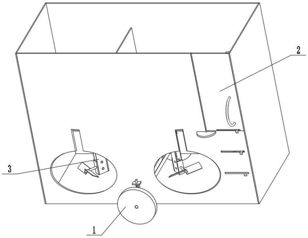
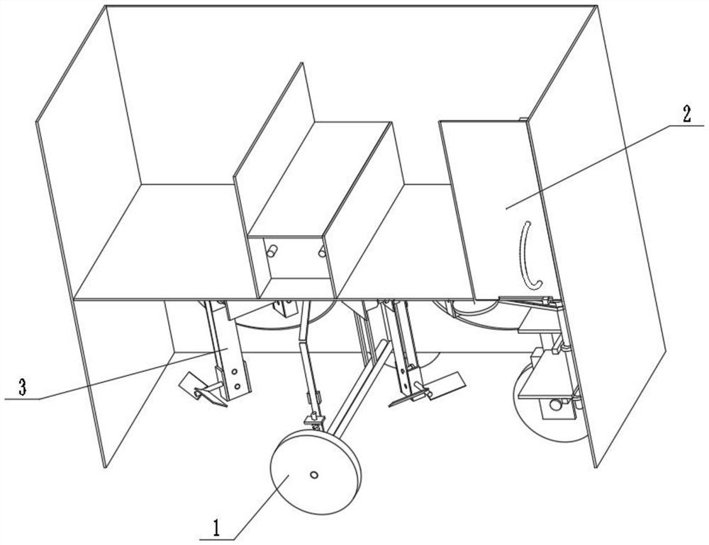
[0028] Combine below figure 1 , figure 2 , image 3 , Figure 4 , Figure 5 , Image 6 , Figure 7 , Figure 8 , Figure 9 , Figure 10 , Figure 11 , Figure 12 , Figure 13 Describe this embodiment. The present invention relates to folding multi-rotor flying vehicle equipment, more specifically, a folding multi-rotor flying double-shock-absorbing vehicle equipment, including a traveling mechanism 1, a linkage door 2, and a folding multi-rotor mechanism 3. When traveling on the ground, the device can absorb shocks for itself, the device can drive the stairs out when the door is opened to allow the operator to get on the car conveniently, and the device can fly in the air.
[0029] The traveling mechanism 1 is connected with the linkage door 2, and the folding multi-rotor mechanism 3 is connected with the traveling mechanism 1.
specific Embodiment approach 2
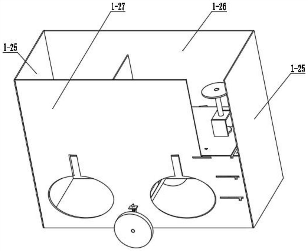
[0031] Combine below figure 1 , figure 2 , image 3 , Figure 4 , Figure 5 , Image 6 , Figure 7 , Figure 8 , Figure 9 , Figure 10 , Figure 11 , Figure 12 , Figure 13 This embodiment will be described. This embodiment will further describe the first embodiment. The traveling mechanism 1 includes a motor mounting plate 1-1, a motor 1-2, a motor shaft 1-3, a friction belt 1-4, and a transmission shaft a1- 5. Transmission shaft b1-6, power wheel 1-7, hinged plate a1-8, hinged plate b1-9, sliding block 1-10, sliding shaft 1-11, sliding return spring 1-12, chute 1-13 , Limit plate 1-14, limit shaft 1-15, limit spring 1-16, steering wheel 1-17, direction shaft 1-18, front wheel damping spring 1-19, bearing plate 1-20, bearing plate Connecting plate 1-21, front wheel connecting block 1-22, front wheel shaft 1-23, front wheel 1-24, connecting plate a1-25, connecting plate b1-26, connecting plate c1-27, connecting plate d1-28, Connecting plate e1-29, connecting pl...
specific Embodiment approach 3
[0033] Combine below figure 1 , figure 2 , image 3 , Figure 4 , Figure 5 , Image 6 , Figure 7 , Figure 8 , Figure 9 , Figure 10 , Figure 11 , Figure 12 , Figure 13 Describe this embodiment, this embodiment will further explain the first embodiment, the linkage door 2 includes a handle 2-1, a revolving door 2-2, a hinge column 2-3, a large gear 2-4, and a pinion 2-5 , linkage shaft a2-6, linkage belt 2-7, linkage shaft b2-8, linkage gear 2-9, linkage rack 2-10, linkage rack connecting plate 2-11, stair plate a2-12, stair plate b2 -13, stair plate c2-14, magnetic strip 2-15, handle 2-1 is connected with revolving door 2-2, revolving door 2-2 is hinged with connecting plate c1-27 through hinge column 2-3, and large gear 2 -4 is connected with the hinge column 2-3, the pinion 2-5 is meshed with the bull gear 2-4, the linkage shaft a2-6 is connected with the pinion 2-5, and the linkage belt 2-7 is frictionally connected with the linkage shaft a2-6 , the lin...
PUM
 Abstract
Description
Claims
Application Information
 - R&D
- Intellectual Property
- Life Sciences
- Materials
- Tech Scout
- Unparalleled Data Quality
- Higher Quality Content
- 60% Fewer Hallucinations
Browse by: Latest US Patents, China's latest patents, Technical Efficacy Thesaurus, Application Domain, Technology Topic, Popular Technical Reports.
© 2025 PatSnap. All rights reserved.Legal|Privacy policy|Modern Slavery Act Transparency Statement|Sitemap|About US| Contact US: help@patsnap.com


