A new energy vehicle charging system

A new energy vehicle and charging system technology, applied in the field of new energy vehicles, can solve the problems of limited installation location and range, limited charging parking spaces, and small number of parking spaces, so as to save installation space and equipment, avoid impurities and dust, and ensure normal operation. effect used

Active Publication Date: 2021-09-28
中程数智信息技术南京有限公司
View PDF5 Cites 0 Cited by
  • Summary
  • Abstract
  • Description
  • Claims
  • Application Information

AI Technical Summary

Problems solved by technology

[0004] First, the charging box is only installed on the parking space close to the wall, resulting in limited charging parking spaces, low coverage of charging parking spaces, and harsh installation conditions for charging boxes
[0005] Second, since the charging pile needs to be installed in a non-parking location close to the charging parking space, more non-parking locations need to be preset to install the charging pile. Less in quantity
[0006] In summary, the inventors found that the existing wall-type charging boxes have limited installation locations and ranges, and need to rely on walls for installation, which is difficult to popularize. The existing post-type charging piles need to occupy non-parking spaces, resulting in a reduction in the number of underground parking spaces.

Method used


Image

  • A new energy vehicle charging system
  • A new energy vehicle charging system
  • A new energy vehicle charging system

Examples


Embodiment 1

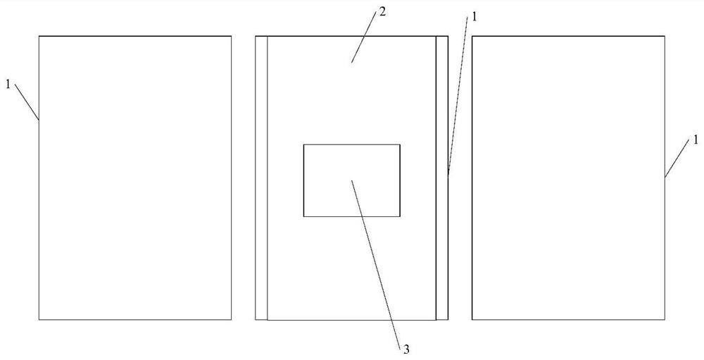
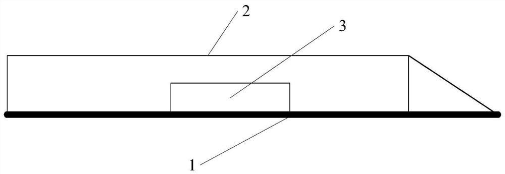
[0054] Please refer to figure 1 , figure 1 It is a schematic diagram of the distribution of the charging system for new energy vehicles, figure 2 It is a schematic structural diagram of a charging system for a new energy vehicle. Embodiment 1 of the present invention provides a charging system for a new energy vehicle. The system includes:

[0055] Box 2, the lower surface of the box is fixed on the preset parking space 1, the vertical centerline of the box coincides with the vertical centerline of the parking space, the length of the box matches the length of the parking space, and the width of the box is smaller than that of the preset parking space Width and greater than the body width of the preset vehicle, a cavity is provided in the box, a charging device 3 for charging the vehicle parked on the preset parking space is installed in the cavity, and a charging device 3 for charging in the charging device is installed on the side of the box body. The first point of entry...

Embodiment 2

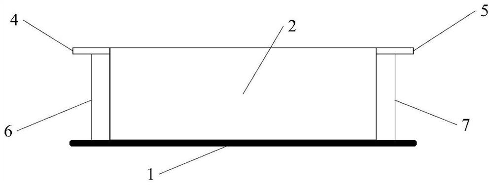
[0060] Please refer to image 3 , image 3 It is a schematic diagram of the installation of the first pedal and the second pedal. Because the vehicle is parked on the box body, and the box body has a certain height, the body of the vehicle becomes higher at this time, that is, the height of the vehicle chassis from the ground becomes higher. Higher, which makes the distance from the ground higher when the user opens the door to get off or get on the car, and it is not easy to get off or get on the car or step on the air. In order to facilitate the user to get off and get on the car and improve the safety of the system, the present invention implements The system in Example 2 also includes: a first control terminal, a first pedal 4, a second pedal 5, a first telescopic rod 6, a second telescopic rod 7 and a first controller;

[0061]The first pedal is located on the left side of the cabinet, the lower end of the first telescopic rod is fixed in the preset parking space on the ...

Embodiment 3

[0065] Please refer to Figure 4 , Figure 4 It is a structural schematic diagram of the pedal structure. On the basis of the third embodiment, the system in this embodiment also includes: several pressure sensors, a second controller and 4 pedal structures;

[0066] Wherein, when the vehicle is parked on the casing, each pedal structure corresponds to a door of the vehicle, and the pedal structure includes: the third pedal 8, the third telescopic rod 9, the first fixed bracket 10, the first support column 11 , the first slider 12, the second support column 13 and the second slider 14;

[0067] A number of pressure sensors are evenly distributed on the first pedal and the second pedal; the side of the box is provided with a second entrance for the third pedal; one end of the third pedal is connected to one end of the third telescopic rod, and the second The other end of the three telescopic rods is connected with the upper end of the first fixed frame; the lower end of the f...


PUM


Abstract

The invention discloses a charging system for new energy vehicles. The system includes: a box body, the lower surface of which is fixed on a preset parking space, the vertical center line of the box body coincides with the vertical center line of the parking space, and the box body The length matches the length of the parking space. The width of the box body is smaller than the width of the preset parking space and larger than the width of the preset vehicle body. There is a cavity in the box, and a device for charging the vehicle parked in the preset parking space is installed in the cavity. The charging device, the side of the box is provided with the first entrance for the charging gun in the charging device to enter and exit; this system enables the parking space not close to the wall to install the charging device while not occupying the non-parking area, the system does not occupy the non-parking area , and does not require a wall-mounted charging box.

Description

technical field [0001] The invention relates to the field of new energy vehicles, in particular to a charging system for new energy vehicles. Background technique [0002] With the intensification of energy problems, new energy vehicles have gradually become mainstream vehicles, such as electric vehicles. The biggest problem currently faced by electric vehicles in use is the charging problem. In the prior art, there are two types of charging equipment for electric vehicles in underground parking spaces, one is a charging box hung on the wall, which is suitable for parking spaces close to the wall, and the other is a charging box installed on the ground Charging piles, because some parking spaces are far away from the wall or pillars, it is impossible to install charging boxes, and only charging piles installed on the ground can be installed. It is not a parking space, and corresponding protective fences or roadblock facilities need to be set up to prevent vehicles from coll...

Claims


Application Information

Patent Timeline
Patent Type & Authority Patents(China)
IPC IPC(8): B60L53/35B60L53/16B60L53/30B60L53/60E04H6/42
CPCB60L53/16B60L53/30B60L53/35B60L53/60E04H6/42Y02T10/70Y02T10/7072Y02T90/12Y02T90/14
Inventor 鲍卫陈子奇赵淑芳
Owner 中程数智信息技术南京有限公司
Why Eureka
Try Eureka