Carrier landing device for vertical take-off and landing aircraft and ship

A technology for vertical take-off and landing and aircraft, applied in the field of ships, can solve the problems of difficult docking of the upper platform, difficult docking control between the aircraft and the lift-off platform, and slow landing gear of the aircraft 50, so as to avoid the effect of unable to dock.

Pending Publication Date: 2020-12-25
魏荣亮
View PDF0 Cites 1 Cited by
  • Summary
  • Abstract
  • Description
  • Claims
  • Application Information

AI Technical Summary

Problems solved by technology

[0013] However, since this landing device requires the aircraft 50 skid landing gear to slowly enter the capture range of the catcher assembly, the skid column of the aircraft can be captured and fixed by the capture claw assembly, but the aircraft is easily affected by wind in the air. , there are certain difficulties in docking with the upper platform, which requires more precise control of the aircraft and the lift-off platform, and the docking control of the aircraft and the lift-off platform is more difficult

Method used


Image

  • Carrier landing device for vertical take-off and landing aircraft and ship
  • Carrier landing device for vertical take-off and landing aircraft and ship
  • Carrier landing device for vertical take-off and landing aircraft and ship

Examples


no. 1 example

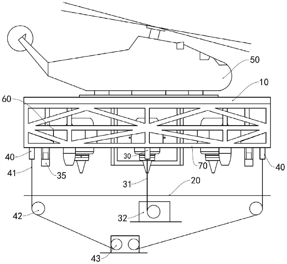
[0096] The ship landing device of this embodiment is mainly applied to the landing of vertical take-off and landing aircraft such as helicopters and vertical lift UAVs on ships, so as to avoid landing accidents.

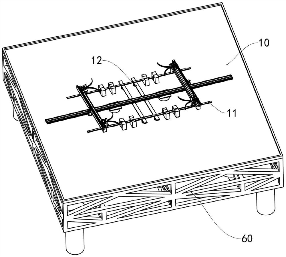
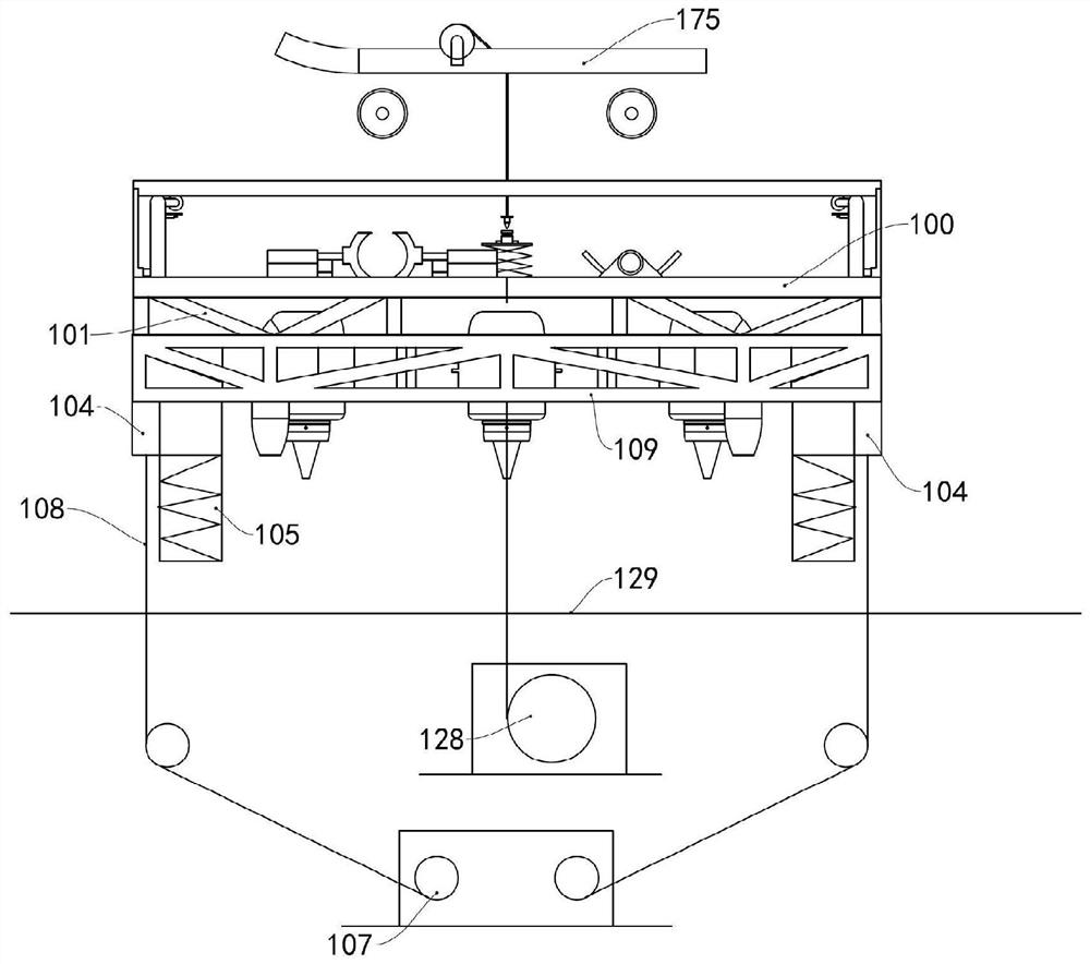
[0097] see image 3 , the ship of this embodiment includes a hull, a deck 129 is arranged on the hull, and a lift-off platform is arranged on the deck 129 . The lift-off platform of the present embodiment includes a three-layer structure, which are respectively an upper platform 100, a power plant layer 101, and a shock absorbing layer 109 arranged in sequence from top to bottom. The upper layer platform 100 is fixed above the power plant layer 101, and the shock absorbing layer 109 is fixed below the power plant layer 101, and the power plant layer 101 is provided with a plurality of trusses. The aircraft 175 is locked on the upper platform 100, and lands on the deck 129 together with the lift-off platform, so that the aircraft 175 can be prevented from directly la...

no. 2 example

[0136]The first embodiment is mainly aimed at the landing of the aircraft with wheeled landing gear, and this embodiment is mainly aimed at the landing of the aircraft with skid-type landing gear. The ship in this embodiment includes a hull, the hull is provided with a deck, and the lift-off platform is arranged on the deck. The lift-off platform includes a three-layer structure, which is an upper platform, a power device layer, and a shock-absorbing layer arranged sequentially from top to bottom, and the three layers are fixedly connected by trusses. The aircraft can be locked on the upper platform and land on the deck together with the lift-off platform. The structures of the upper platform, the power device layer and the shock absorbing layer are the same as those of the first embodiment, and will not be repeated here.

[0137] see Figure 12 , Figure 13 and Figure 14 , the upper platform 200 is provided with a tensioning assembly, the tensioning assembly in this embo...

no. 3 example

[0160] The present embodiment is mainly aimed at the landing of the aircraft with the skid type landing gear. The ship in this embodiment includes a hull, the hull is provided with a deck, and the lift-off platform is arranged on the deck. The lift-off platform includes a three-layer structure, which is an upper platform, a power device layer, and a shock-absorbing layer arranged sequentially from top to bottom, and the three layers are fixedly connected by trusses. The aircraft can be locked on the upper platform and land on the deck together with the lift-off platform. The structures of the upper platform, the power device layer and the shock absorbing layer are the same as those of the first embodiment, and will not be repeated here.

[0161] see Figure 19 , two skid installation slots 301 are arranged above the upper platform 300, and each skid 371 of the aircraft can be installed in one skid installation slot 301 respectively. A through hole is provided in the middle ...


PUM


Abstract

The invention provides a carrier landing device for vertical take-off and landing aircraft and a ship. The carrier landing device comprises a lift-off platform, wherein a plurality of power devices which are used for driving the lift-off platform to ascend or descend are arranged on the lift-off platform; a power cable and an exploring tube are arranged below the lift-off platform, a pull-down cable is arranged in the exploring tube, and a damping landing frame is further arranged below the lift-off platform; and the lift-off platform comprises an upper platform, the upper platform is locatedon the upper end of the lift-off platform, a tensioning assembly is arranged on the upper platform, and the tensioning assembly is used for pulling the aircraft and the upper platform together. The ship is provided with the carrier landing device. According to the carrier landing device, large impact on a deck when the aircraft lands on the deck can be avoided, and the carrier landing control of the aircraft is simple.

Description

technical field [0001] The invention relates to the field of landing aids for shipborne vertical take-off and landing aircraft, in particular to a landing device for vertical take-off and landing aircraft and a ship with the landing device. Background technique [0002] Shipborne vertical take-off and landing aircraft, such as helicopters and unmanned aerial vehicles, need to rely on the landing device when landing on the ship, and the existing landing device mainly makes the aircraft perform a rigid landing on the ship. Taking helicopters as an example, the landing devices of helicopters mainly include three types of landing devices: "pull-down" type, "harpoon-grid" type, and "landing aid net" type. [0003] The drag-and-drop landing device is mainly composed of the index, index winch, main probe, tail probe, and the drag and drop winch, clamping mechanism and control room on the ship. When the helicopter is ready to land, the helicopter hovers at a height of 6 to 8 meters...

Claims


Application Information

Patent Timeline
Patent Type & Authority Applications(China)
IPC IPC(8): B64F1/02B64F1/12
CPCB64F1/02B64F1/125
Inventor 魏荣亮
Owner 魏荣亮
Why Eureka
Try Eureka