Method for detecting operation state of sliding door lock of platform door system

A technology of operating state and detection method, which is applied to non-mechanical transmission-operated locks, timing locks, building locks, etc., can solve the problems of no sliding door lock operating state detection, etc., to avoid equipment failure, reduce maintenance costs, The effect of ensuring accuracy

Active Publication Date: 2020-12-25
牛玉涛
View PDF5 Cites 3 Cited by
  • Summary
  • Abstract
  • Description
  • Claims
  • Application Information

AI Technical Summary

Problems solved by technology

[0009] Aiming at the defects and problems that there is currently no technical means for detecting the operating state of the sliding door lock, the present invention provides a method for detecting the operating state of the sliding door lock in the platform door system

Method used


Image

  • Method for detecting operation state of sliding door lock of platform door system
  • Method for detecting operation state of sliding door lock of platform door system
  • Method for detecting operation state of sliding door lock of platform door system

Examples


Embodiment 1

[0036] Embodiment 1: This embodiment provides a method for detecting the operating state of the sliding door lock in the platform door system. The detection method detects the operating state of the sliding door lock in the platform door system by calculating time, including the following steps:

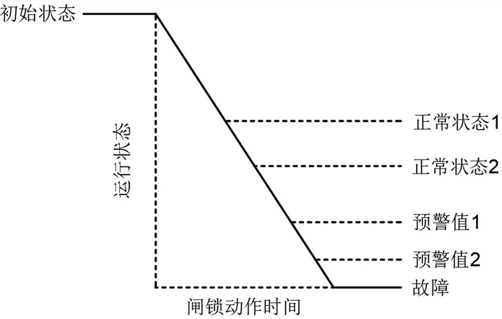
[0037] When opening the door, record the time when each sliding door lock mechanism of the same type on the whole line network sends out the electromagnet pull-in signal T a , The time to receive the action signal of the lock in place switch T b , to calculate the unlocking time of each sliding door lock ΔT 1 , ΔT 1 = T b - T a ;Divide the unlocking time of the sliding door lock into normal state 1, normal state 2, warning value 1, warning value 2 and fault value according to the length of time, and establish the unlocking time fault with the time as the abscissa and the running state as the ordinate Threshold curve, the curve status is as figure 1 shown.

[0038] When t...

Embodiment 2

[0048] Embodiment 2: The similarities between this embodiment and Embodiment 1 will not be repeated. The difference is that when the detection requirements cannot be met by the close position switch and the lock position switch, the electromagnet is detected by the door state detection module. Action time of instruction, close limit switch and lock limit switch.

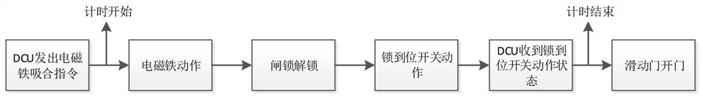
[0049] like Figure 4 As shown in the figure, when the DCU receives the door opening command, it sends the electromagnet pull-in command, and the detection module starts timing when it detects this state; after the electromagnet receives the pull-in command, it controls the lock to unlock, and after the unlocking is completed, the lock position detection switch operates , when the detection module detects the action state of the lock in-position switch, the detection module ends the timing, completes the record of the unlocking time, and uploads the data to the intelligent operation and maintenance host.

[0050] li...


PUM


Abstract

The invention belongs to the technical field of operation and maintenance monitoring, and particularly relates to a method for detecting the operation state of a sliding door lock of a platform door system. According to the detection method, the time difference between the time when the sliding door lock sends out an electromagnet attraction signal and the time when the sliding door lock receivesa lock in-place switch action signal is calculated, the time difference between the time when the sliding door lock receives a closing in-place switch action signal and the time when the sliding doorlock receives the lock in-place switch action signal is calculated, and the operation state of the sliding door lock in the platform door system is detected through a time calculation method. Detection is easy, accuracy is high, the operation reliability of the sliding door lock can be greatly improved, and the equipment failure rate is reduced.

Description

technical field [0001] The invention belongs to the technical field of operation and maintenance monitoring, and in particular relates to a method for detecting the operating state of a sliding door lock of a platform door system. Background technique [0002] The sliding door lock device of the platform door system is installed in the top box, located in the center above the sliding door, including the mechanical part and the electronic part; the mechanical part ensures that the sliding door can be locked after running to the locked position, and the electronic part ensures that it can pass through the travel switch Feedback the status of the sliding door to the DCU of each door unit. At present, the sliding door lock devices commonly used in the platform door system all adopt the detection mode of the closed limit switch and the locked limit switch to detect the state of the sliding door. [0003] Through years of experience in on-site maintenance of platform door equipme...

Claims


Application Information

Patent Timeline
Patent Type & Authority Applications(China)
IPC IPC(8): E05B65/08E05B47/00E05B43/00
CPCE05B65/08E05B47/0002E05B43/005E05B2047/0068E05B2047/0069
Inventor 牛玉涛
Owner 牛玉涛
Why Eureka
Try Eureka