
Radio shunting signal lamp indication system and method with function of shunting route guidance in non-interlocking areas

A shunting and approach technology, applied in the field of shunting, can solve the problems of high requirements for shunters or switchers, increasing the labor intensity of professionals, and unable to ensure the safety and efficiency of high-density shunting operations.

Active Publication Date: 2019-09-06
昆明聚讯科技有限公司
View PDF6 Cites 9 Cited by
  • Summary
  • Abstract
  • Description
  • Claims
  • Application Information

AI Technical Summary

Problems solved by technology

According to the paper shunting operation plan, the switcher manually observes the shunting position and combines the shunting operation time and plan to discharge the route in a timely manner. After discharging the route, draw a completed mark on the corresponding shunting coupler. Before discharging into the road, it is necessary to send shunting personnel to manually check the opening of the road. After the inspection is completed, they will send a voice message through the hand-held intercom for shunting to inform all shunting crews. This operation method increases the labor intensity of the professionals. The requirements for the operator or switchman are relatively high
In addition, in stations where multiple shunting machines are operating at the same time, and at stations with busy train operations, the labor intensity of shunting personnel or switchmen is even greater. This traditional operation method, which only relies on the self-control and mutual control of operators, has been unable to guarantee high-density dispatching. Safety and efficiency requirements for truck operations

Method used


Image

  • Radio shunting signal lamp indication system and method with function of shunting route guidance in non-interlocking areas
  • Radio shunting signal lamp indication system and method with function of shunting route guidance in non-interlocking areas
  • Radio shunting signal lamp indication system and method with function of shunting route guidance in non-interlocking areas

Examples


Embodiment Construction

[0140] The present invention will be further described in detail below in conjunction with the examples.

[0141] Those skilled in the art will understand that the following examples are only for illustrating the present invention and should not be considered as limiting the scope of the present invention. If no specific technique or condition is indicated in the examples, it shall be carried out according to the technique or condition described in the literature in this field or according to the product specification. The materials or equipment used are not indicated by the manufacturer, and they are all conventional products that can be obtained through purchase.

[0142] Those skilled in the art can understand that the relevant modules involved in the present invention and the functions realized are carried out on the improved hardware and the device, device or system formed by it, by carrying conventional computer software programs in the prior art or The relevant agreeme...


PUM


Abstract

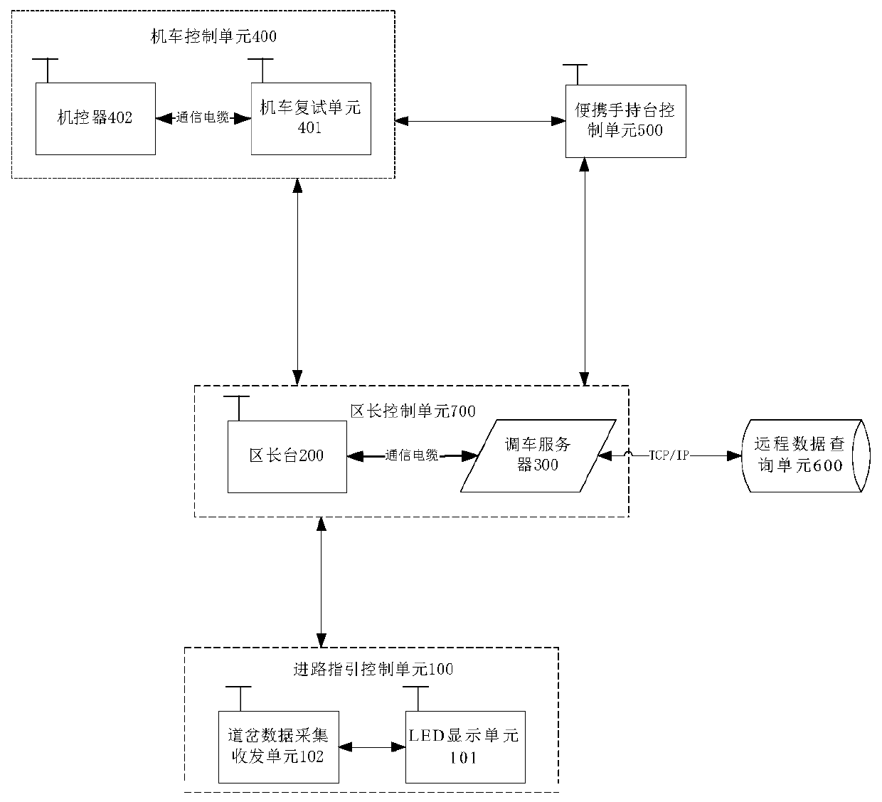
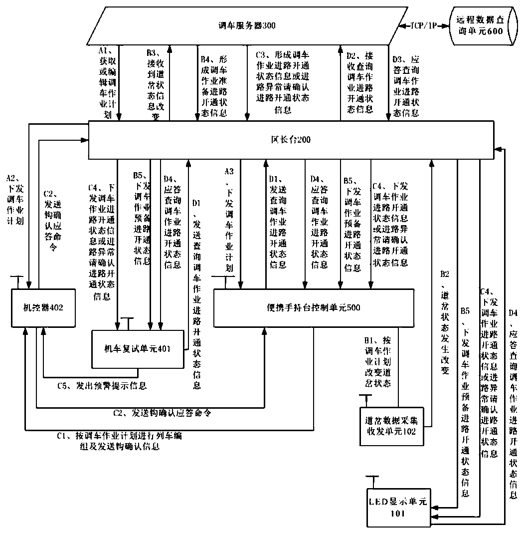
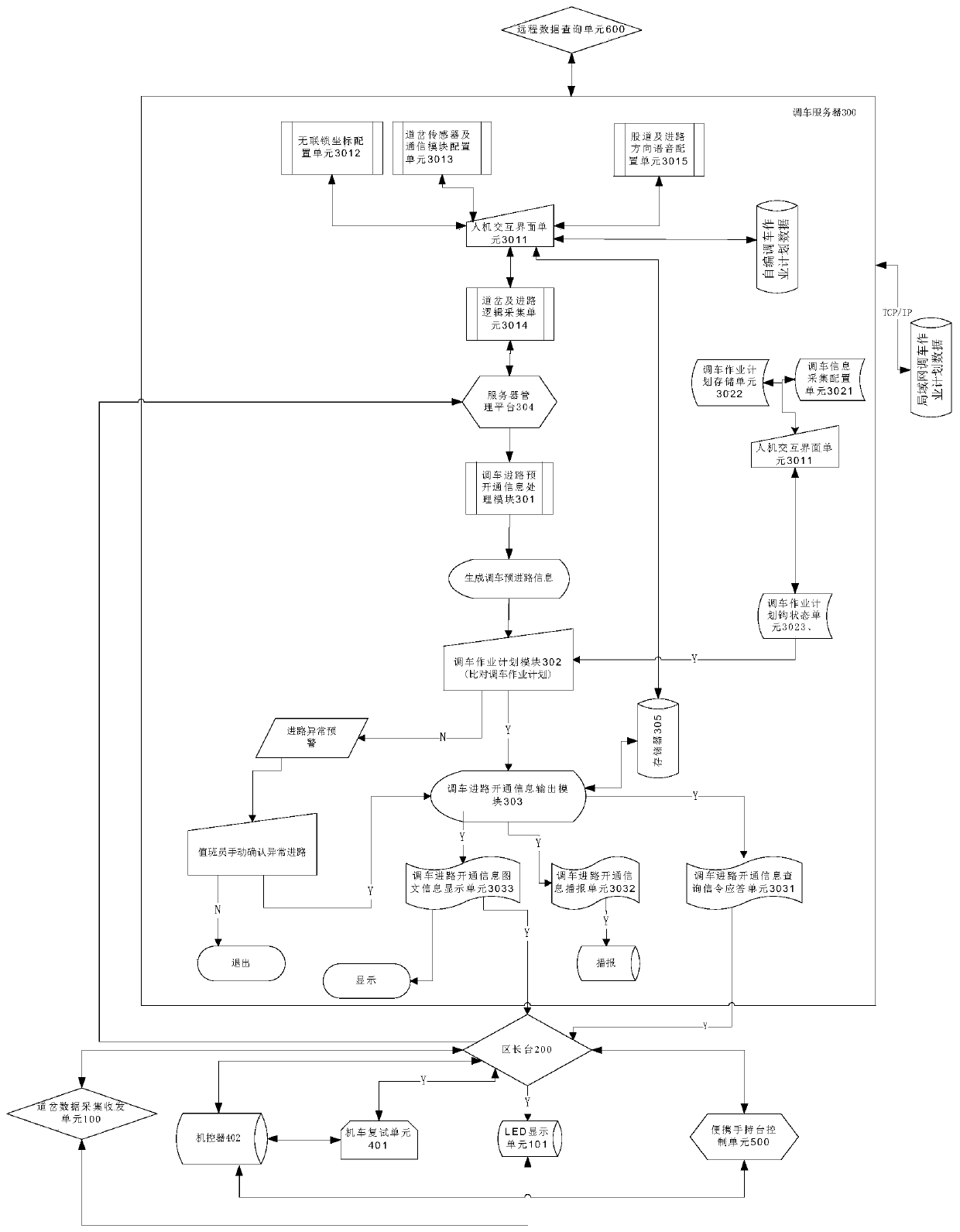
The invention relates to a radio shunting signal lamp indication system and method with a function of shunting route guidance in non-interlocking areas, and belongs to the technical field of shuntingin the railway transportation process. The radio shunting signal lamp indication system comprises a locomotive control unit, an area manager control unit, a route guidance control unit, a portable handheld radio control unit, a remote data query unit and other structures. In addition to a function of command for shunting operations, the radio shunting signal lamp indication system also has a function of route query for the shunting operations, and can avoid incorrect operations or incorrect confirmation caused by human factors, thereby avoiding the occurrence of incorrect routing, switch splitting and even train derailment accidents. The radio shunting signal lamp indication system not only provides a safety guarantee for the shunting operations but also reduces the labor intensity of operators, thereby improving the efficiency of the shunting operations and the sorting capacity of a station.

Description

technical field [0001] The invention belongs to the technical field of shunting during railway transportation, and in particular relates to a wireless shunting light display system and method with the function of guiding the route of shunting without interlocking. Background technique [0002] The shunting operation is an important part of the railway transportation process, and the shunting operation in the railway yard is mainly carried out in the non-centralized shunting operation area. With the development of railway transportation in the direction of high speed, heavy load, and high density, the safety production pressure faced by the train service system is increasing. The confirmation of the existing non-interlock shunting operation route is mainly through the manual arteries of the shunting personnel. , Returning the way to complete, its main basis is the visual sign light (card) signal, and safety monitoring also mainly relies on manual completion. In the process o...

Claims


Application Information

Patent Timeline
IPC IPC(8): B61L27/00B61L21/06B61L21/08
CPCB61L21/06B61L21/065B61L21/08B61L27/00
Inventor 李涛
Owner 昆明聚讯科技有限公司
Learn More