
A clutch slip control device and control method

A control device and clutch technology, applied in the direction of clutch, mechanical equipment, etc., can solve the problems of energy loss, reduce the life of the drive train of comfort and maneuverability, and achieve the effect of reducing slip rate, shortening working time, and convenient operation.

Active Publication Date: 2021-12-28
XIANGTAN UNIV
View PDF8 Cites 0 Cited by
  • Summary
  • Abstract
  • Description
  • Claims
  • Application Information

AI Technical Summary

Problems solved by technology

The clutch combination can rigidly transmit the power output from the engine to the gearbox, which improves the system transmission efficiency and reduces energy loss, but it also brings adverse consequences, because the noise and vibration caused by the torque fluctuation generated by the engine fuel combustion It will be directly transmitted to the drive train of the car, reducing the comfort of the ride, the handling of the car and the life of the drive train
On the other hand, when the clutch is disengaged, the transmission of engine torque fluctuations to the drive train is effectively blocked, but because part of the power of the engine is transmitted to the gearbox in the form of hydraulic power, a large amount of energy loss will occur

Method used


Image

  • A clutch slip control device and control method
  • A clutch slip control device and control method
  • A clutch slip control device and control method

Examples


Embodiment Construction

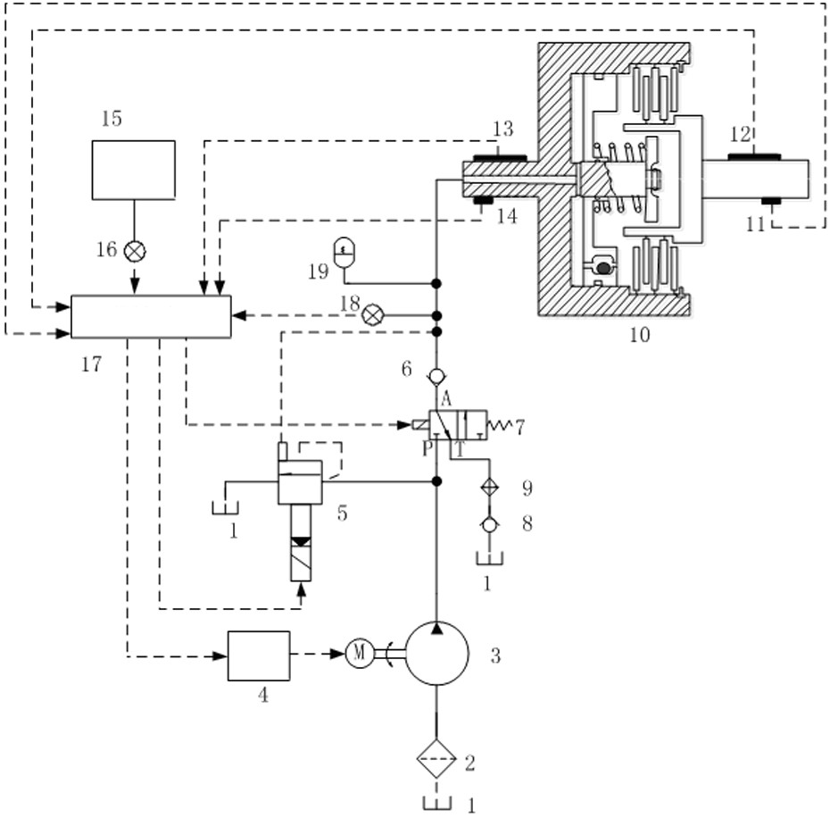
[0029] The present invention will be further described below in conjunction with the accompanying drawings.

[0030] Such as figure 1 As shown, the clutch slip friction control device of the present invention includes a clutch 10, a hydraulic device and a fuzzy controller 17; the input shaft of the clutch is provided with a torque sensor 13 and a rotational speed sensor 14, and the output shaft of the clutch is provided with a torque sensor 12 And speed sensor 11, engine place is provided with a throttle opening sensor 16, and clutch oil inlet and outlet place is provided with a pressure sensor 18.

[0031] The hydraulic device includes a fuel tank 1, a filter 2, an oil pump 3, an electromagnetic proportional pilot relief valve 5, a one-way valve I6, an electromagnetic valve 7, a spring accumulator 19, a cooler 9 and a one-way valve II8; The oil inlet of the oil pump 3 is connected with the oil outlet of the filter 2, and the oil inlet of the filter 2 is connected with the fu...


PUM


Abstract

The invention discloses a clutch sliding friction control device and a control method. The device comprises a clutch, a hydraulic device and a fuzzy controller; There is a pressure sensor, and the hydraulic device includes an oil pump; the oil inlet of the oil pump is connected with the oil tank; the oil outlet of the oil pump is connected with the oil port P of the solenoid valve through the oil inlet pipe; the oil port A of the solenoid valve is connected with the oil inlet of the one-way valve I , the oil port T of the solenoid valve communicates with the oil tank; the oil outlet of the check valve I communicates with the oil inlet and outlet of the clutch through the oil pipe, and the oil pipe is connected to the accumulator through the pipeline; the oil inlet pipe is connected with the electromagnetic proportional pilot overflow through the pipeline The oil inlet of the valve, the oil pipe connecting the one-way valve I and the clutch is connected to the external control port of the electromagnetic proportional pilot relief valve through the pipeline. The invention has the advantages of simple structure and high control precision, so that the clutch always works in the best sliding friction zone, and realizes the balance between the dynamic performance and the smoothness of the clutch.

Description

technical field [0001] The invention belongs to the technical field of clutch control, and in particular relates to a clutch slip control device and a control method. Background technique [0002] The starting clutch enables the gradual engagement between the engine and the transmission, thereby ensuring a smooth start of the car. The clutch combination can rigidly transmit the power output from the engine to the gearbox, which improves the system transmission efficiency and reduces energy loss, but it also brings adverse consequences, because the noise and vibration caused by the torque fluctuation generated by the engine fuel combustion It will be directly transmitted to the drive train of the car, reducing the comfort of the ride, the handling of the car and the life of the drive train. On the other hand, when the clutch is disengaged, the transmission of engine torque fluctuations to the drive train is effectively blocked, but because part of the power of the engine is ...

Claims


Application Information

Patent Timeline
Patent Type & Authority Patents(China)
IPC IPC(8): F16D48/06
CPCF16D48/06F16D2500/1045F16D2500/30415F16D2500/30426F16D2500/30406
Inventor 刘金刚郑剑云傅兵赵又红姜胜强王高升
Owner XIANGTAN UNIV
Learn More