Pre-heating spray-hole type static mixer

A technology of static mixers and spray holes, applied in the direction of fluid mixers, mixers, mixing methods, etc., can solve the problems of not realizing preheating, etc., reduce the ammonia slip rate, shorten the mixing distance, and promote uniform mixing Effect

Active Publication Date: 2013-12-18
HARBIN ENG UNIV
View PDF4 Cites 0 Cited by
  • Summary
  • Abstract
  • Description
  • Claims
  • Application Information

AI Technical Summary

Problems solved by technology

At present, there is no static mixer that integrates the three functions of preheating, spraying urea aqueous solution, and mixing ammonia and flue gas.

Method used


Image

  • Pre-heating spray-hole type static mixer
  • Pre-heating spray-hole type static mixer
  • Pre-heating spray-hole type static mixer

Examples


Embodiment approach 1

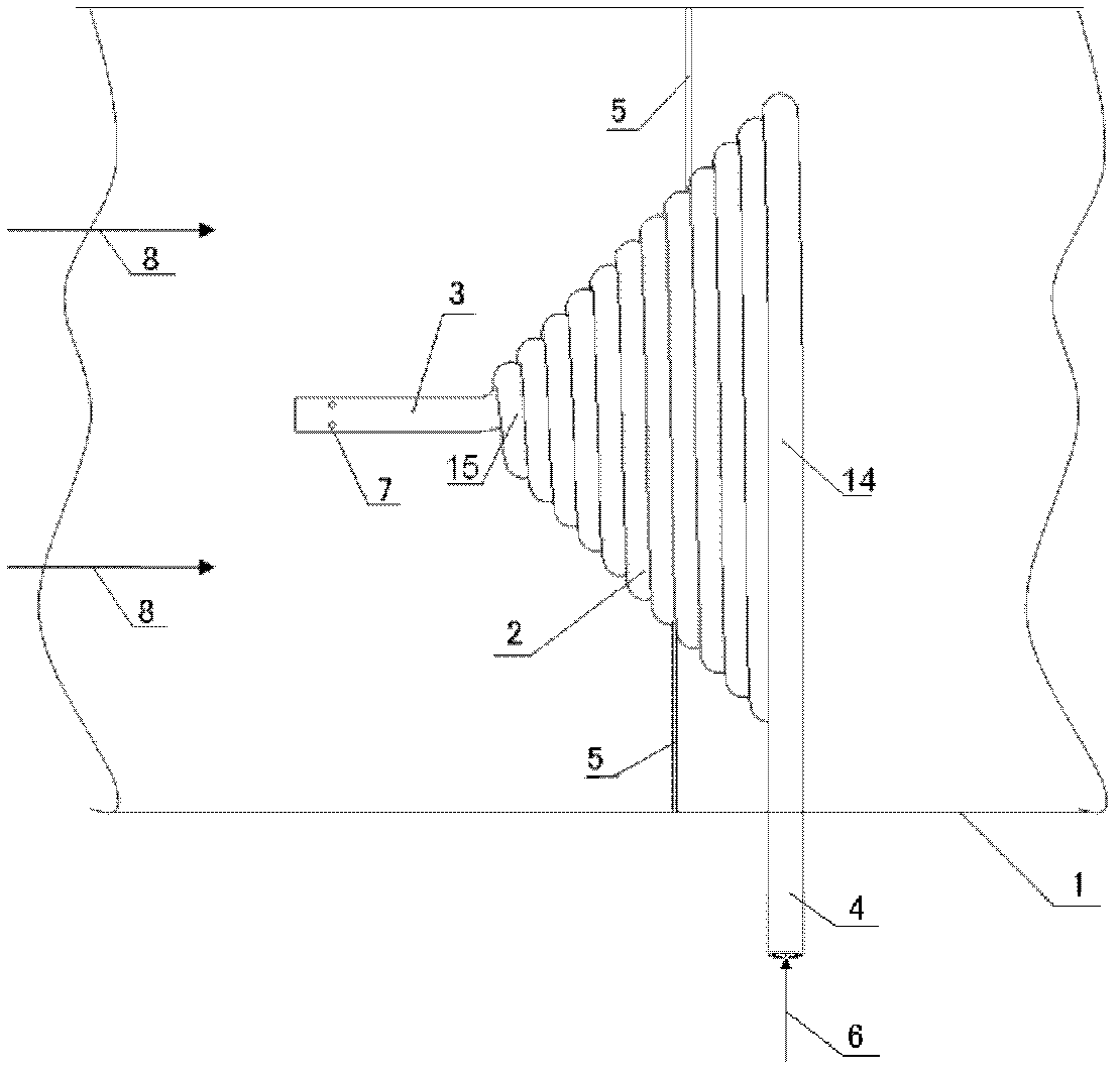
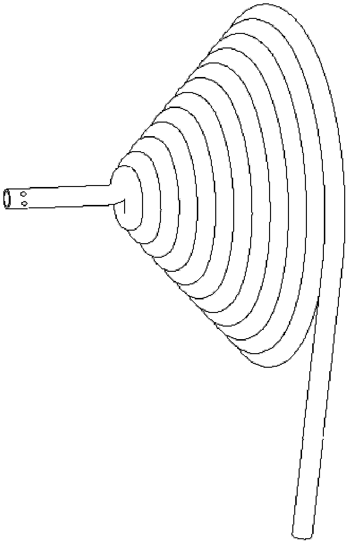
[0033] combine figure 1 and figure 2 , the outer ring port 14 of the preheating pipe is connected to the inlet pipe 4, the inner ring port 15 is connected to the nozzle pipe 3, a ring of nozzle holes 7 is opened on the side wall of the pipe at the closed end of the nozzle pipe 3, and the closed end is arranged at The center of the cross section of the flue 1 is located, and the end face faces the inflow direction of the flue gas 8 . The preheating pipe 2 is fixed to the inner wall of the flue 1 through the support beam 5, and can also be connected to the flange 9 through the support beam 5, such as Figure 9 shown. The preheating tube 2 can be wound into sheets, such as Figure 5 shown, it can also be wound into a tapered shape, such as Image 6 shown. However, no matter what shape of preheating pipe is used, it should be ensured that there is no gap between the spiral center of the preheating pipe 2 and the adjacent spiral pipes, so that the flue gas 8 cannot pass throu...

Embodiment approach 2

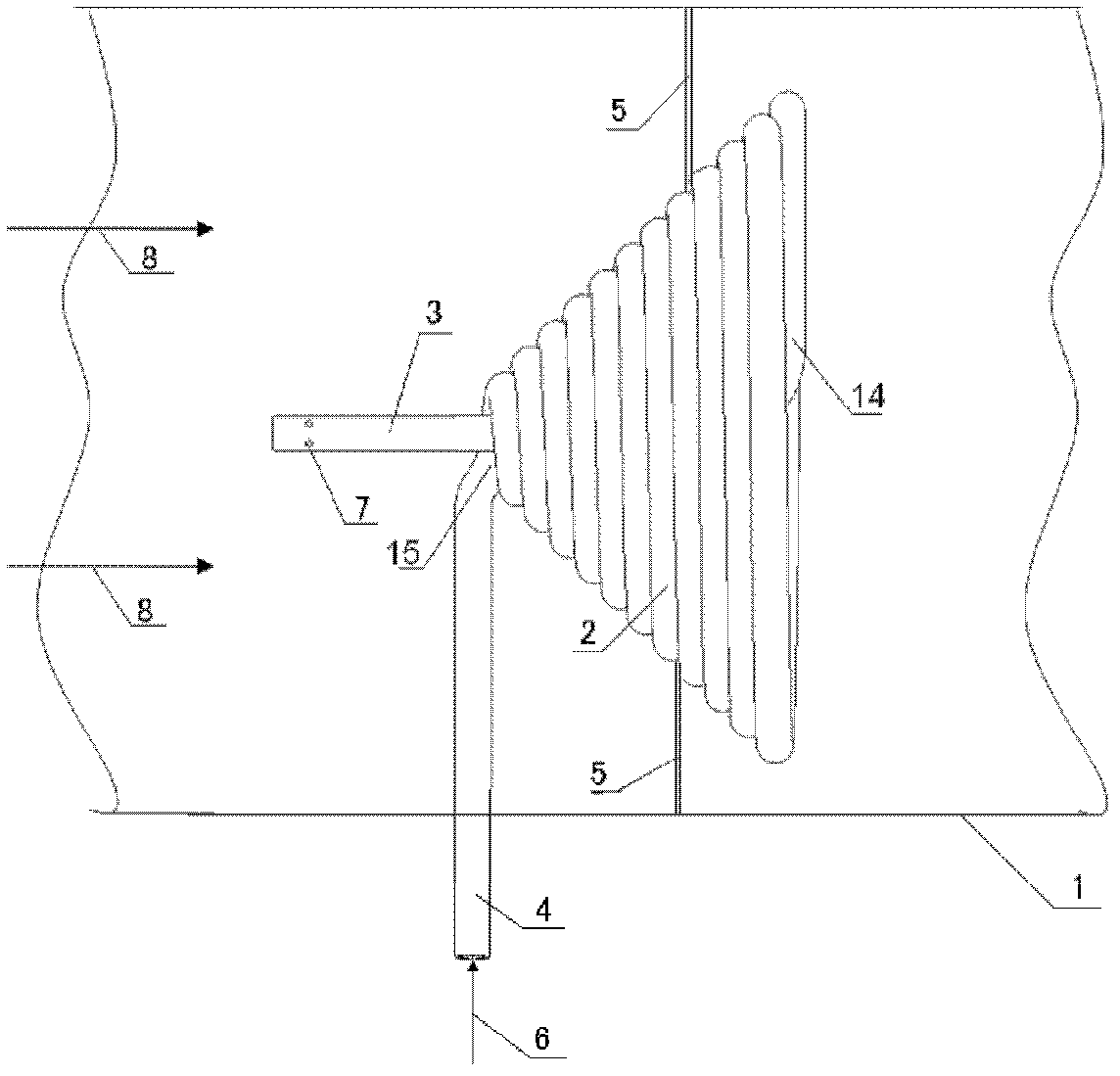
[0034] Embodiment 2: Combining image 3 and Figure 4 The difference from Embodiment 1 is that the outer ring port 14 of the preheating pipe is connected to the nozzle pipe 3 , and the inner ring port 15 is connected to the inlet pipe 4 .

Embodiment approach 3

[0035] Embodiment 3: On the basis of Embodiment 1 and Embodiment 2, after the closed end of the orifice pipe is arranged in the preheating pipe, the end face of the closed end faces or faces away from the inflow direction of the flue gas.


PUM


Abstract

The invention aims to provide a pre-heating spray-hole type static mixer, comprising a pre-heating pipe, a spray-hole pipe and an inlet pipe, wherein the pre-heating pipe is arranged in a flue, the inlet pipe is inserted into the flue, the pre-heating pipe is spirally coiled, two ends of the pre-heating pipe are respectively connected with the spray-hole pipe and the inlet pipe, and a supporting beam is fixed on the pre-heating pipe and is fixed on the wall of the flue. The pre-heating spray-hole type static mixer disclosed by the invention is used for pre-heating aqueous urea solution sprayed by a urea SCR (Selective Catalytic Reduction) system to facilitate the aqueous urea solution to quickly evaporate and decompose to generate ammonia gas and also effectively facilitates the ammonia gas to uniformly mix with smoke, thereby largely shortening a mixing distance, improving smoke denitration rate and reducing ammonia slip rate.

Description

technical field [0001] The invention relates to an emission treatment device in the field of diesel engines. Background technique [0002] As we all know, diesel engines have always been the main source of power for ships. Due to the characteristics of marine diesel engines, such as low speed, large excess air coefficient, and large thermal load, the nitrogen oxide emissions of marine diesel engines are relatively high. With the development of the shipping industry, the pollution of the atmospheric environment by the exhaust of the marine diesel engine is also increasing. In the past ten years, with the increasingly strict ship emission regulations in various countries, the application of selective catalytic reduction SCR technology to reduce nitrogen oxide emissions from marine diesel engines has become a new research focus. [0003] The working principle of the SCR method is that under the action of a catalyst, NH3 is used as a reducing agent to selectively react with NO...

Claims


Application Information

Patent Timeline
Patent Type & Authority Patents(China)
IPC IPC(8): B01F5/00B01F3/02B01D53/94B01D53/56B01F23/10
Inventor 田新娜张文平肖友洪张新玉明平剑曹贻鹏柳贡民
Owner HARBIN ENG UNIV
Why Eureka
Try Eureka