Flue gas denitration process for CO exhaust-heat boiler of FCC apparatus

A waste heat boiler and flue gas technology, which is applied in the separation of dispersed particles, chemical instruments and methods, separation methods, etc., can solve the problems of not considering the control of the oxygen content of the boiler, affecting the denitrification effect of the flue gas, and not considering the injection of ammonia gas. , to achieve the effect of facilitating the catalytic reduction and denitration reaction, ensuring the denitration rate and service life, and having no potential safety hazards.

Active Publication Date: 2014-05-07
CHINA PETROLEUM & CHEM CORP +1
View PDF7 Cites 12 Cited by
  • Summary
  • Abstract
  • Description
  • Claims
  • Application Information

AI Technical Summary

Problems solved by technology

This method realizes that the SCR denitrification catalytic reaction unit is arranged inside the waste heat boiler, which reduces the number of equipment and occupies an area. However, only the SCR denitrification catalytic reaction unit is arranged inside the waste heat boiler, and the temperature range of 300-400 ° C is in the CO waste heat boiler. The position inside the boiler is different from that of other boilers, so it is very important to consider the relative position of the ammonia injection position and the SCR denitrification catalytic reaction unit, which directly affects the denitrification effect of the flue gas; and the above patent does not consider how to inject ammonia gas, that is, to meet the The mixing effect of ammonia and flue gas has no safety hazard; at the same time, the problem of controlling the oxygen content of the boiler is not considered. If the oxygen content of the boiler increases, it may lead to a decrease in boiler efficiency

Method used


Image

  • Flue gas denitration process for CO exhaust-heat boiler of FCC apparatus
  • Flue gas denitration process for CO exhaust-heat boiler of FCC apparatus

Examples


Embodiment 1

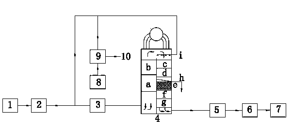
[0035] see figure 1 As shown in the denitration process flow, the regenerated flue gas generated by FCC regenerator 1 has a flow rate of 120,000 Nm 3 / h, the oxygen concentration was 2.3v%, the temperature was 610°C, the pressure was 0.33MPa, and the CO concentration was 6v%.

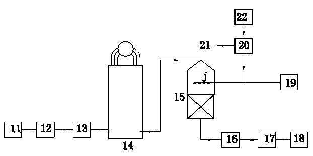
[0036] After the regenerated flue gas is removed by the cyclone dust collector 2 to remove the dust larger than 10mm, a flue gas with a flow rate of 1.25v% of the original regenerated flue gas flow is separated as the ammonia gas dilution gas, the temperature is 610 ℃, and the pressure is 0.33 MPa. The rest of the flue gas is sent to the CO waste heat boiler 4 after the energy is recovered by the flue gas turbine 3 .

[0037] The liquid ammonia 8 enters the evaporator 9 and is evaporated into ammonia gas by the externally supplied steam 10, and the flow rate is 48Nm 3 / h of ammonia with 1500Nm 3 / h After the dilution gas is mixed, the concentration is about 3.0v%. The dilution gas not only dilutes a...


PUM


Abstract

The invention discloses a flue gas denitration process for a CO exhaust-heat boiler of an FCC apparatus. Flue gas produced by an FCC regenerator is dedusted by a deduster, and before entering the CO exhaust-heat boiler, a cloud of flue gas is led out and used as a diluent gas for ammonia gas; and the flow of the diluent gas is 0.1 v%-5.0 v% of that of the original regeneration flue gas. The rest of the flue gas has energy recovered by a flue gas turbine, and is sent into the CO exhaust-heat boiler. The upper part of a high temperature evaporation section of the CO exhaust-heat boiler is provided with an ammonia injection grid, and an SCR denitration catalyst module is arranged between a low temperature evaporation segment and a high temperature economizer. The process provided by the invention uses FCC regeneration flue gas as the diluent gas for ammonia gas to dilute and carry the ammonia at the same time, so as to improve the mixing effect of ammonia gas and flue gas, not increase the rate of oxygen content rate of the CO exhaust-heat boiler, and avoid security risks; at the same time CO removal, waste heat recovery and denitrification of flue gas are accomplished in the CO exhaust-heat boiler, thereby omitting a separate SCR denitration reactor.

Description

technical field [0001] The invention relates to a treatment method for catalytic cracking (FCC) regenerated flue gas, in particular to a selective catalytic reduction (SCR) denitration process for the treatment of regenerated flue gas of an FCC unit in an oil refinery. Background technique [0002] Nitrogen oxides, collectively referred to as NOx, are one of the main sources of air pollution. The most harmful are mainly: NO, NO 2 . The main hazards of NOx are as follows: (1) toxic to humans; (2) toxic to plants; (3) can form acid rain and acid mist; (4) form photochemical smog with hydrocarbons; (5) destroy the ozone layer . [0003] In an oil refinery, FCC (fluid catalytic cracking) process, catalyst particles are repeatedly circulated between a catalytic cracking zone and a catalyst regeneration zone, during which the coke from the cracking reaction on the catalyst particles is removed by air oxidation at high temperature, The removal of the coke deposits restores the ...

Claims


Application Information

Patent Timeline
Patent Type & Authority Applications(China)
IPC IPC(8): B01D53/90B01D53/56
Inventor 李勇刘忠生
Owner CHINA PETROLEUM & CHEM CORP
Why Eureka
Try Eureka